|
Hi old duke,
I will try to answer your questions as posed:
1) I'm afraid I don't know what a unpowered/no battery low voltage continuity tester is, exactly. What you want is a simple test light. A light bulb that shows you 12V power. When you use it, you ground one end of the light and probe with the other end.
2) There's no need to remove the screws holding the flex fuse when removing the speedometer gauge, but I understand it can happen by mistake. Doing that leaves the possibility the connections are disturbed and not functioning when you put it back. With the cluster powered (L-plug in and key in KP-II) check for power on either side of the fuse. Should be both places, of course.
3) The flex fuse is there to prevent fire in the wiring harness if there's a short circuit fault. It won't save the gauge from mis-wiring.
4) Very likely in my remote vision estimate. See #2.
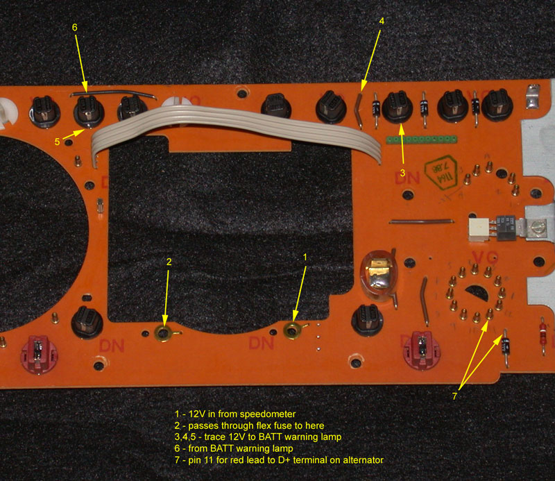
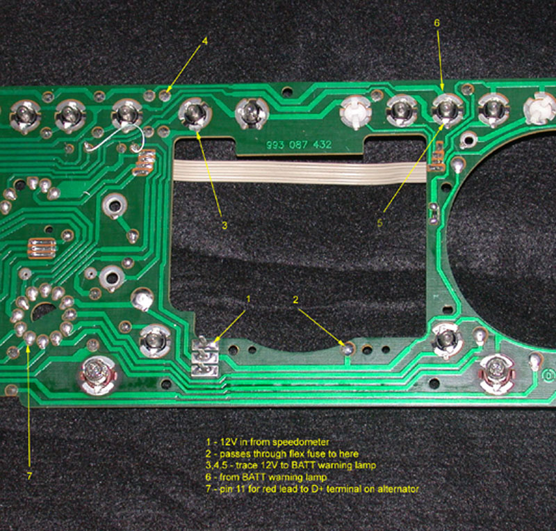
5) Here are marked-up photos of a slightly earlier version of your cluster showing the points where you would expect to see the voltage that comes in on the green/white wire to the speedometer gauge. It was done to help someone find a similar problem as you are experiencing. One of the differences between these photos and your cluster is you have 4 pins where only 3 are shown on this 1989 unit. Remember to check as I suggested earlier-- that your speedometer gauge is properly seated in the pins that protrude from the cluster circuit board.
--
Art Benstein near Baltimore
When a clock is hungry, it goes back four seconds.
|