|
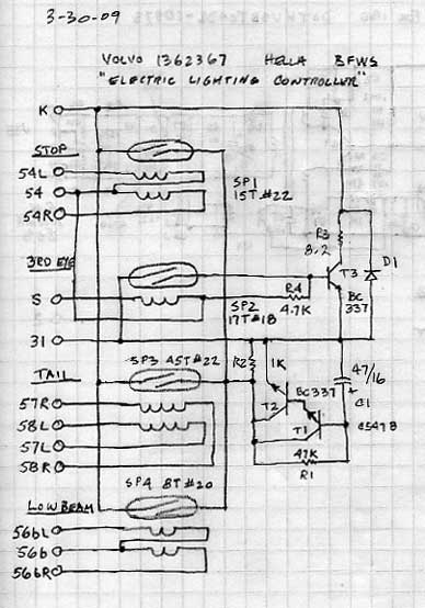
Dave mentions the transistor circuitry. Of course we are all looking to find a "bad part" so we can replace the part and be done. All the interconnections in our car's electrical wiring are "parts" too, and those are the parts which fail most often.
This sensor was reporting a bulb out when the brake pedal was used. I spent the usual half hour cleaning up the bulb sockets in the sedan's tail lights even though they all appeared to be working. Then I turned my focus on the whistle blower.
The clue I should have paid attention to is, with both tail light bulbs removed (for cleaning) the failure light still came on despite the currents to the right and left brake lamps being equal (at zero) and the high-mounted stop light in the rear window was working.
These transistors Dave mentions provide the "negative logic" to test operation of the third brake lamp. The current sensor closes the reed switch when the load to the high mounted brake lamp is present, and the transistors invert that closure to an open circuit for the bulb failure indicator lamp.
So when that circuitry fails, it falsely reports a dead third eye. Fixing the sensor was easy, because all this 3rd eye circuitry is on the very last tier of the sensor's circuit boards - at the back.
TLDR? Reflow the solder. Second time for this unit. First time was for Dave's issue - the brake lamp current not getting passed, and working inside those tiers with a soldering iron isn't as easy as this one.


--
Art Benstein near Baltimore
If you think nobody cares if you're alive, try missing a couple of car payments.
|