|
|
|
Good day all, have a crank, no start condition. Installed a new CPS by Walker. Did a resistance test on the pins, got infinity on pins 1 and 3 to ground. Checked the original CPS that I removed, got 180 ohms on pin 1 to ground. Should I get 180 ohms on pin 3 to ground? Thanks
|
|
|
|
|
Hello all, turns out my main fuel pump was the issue. I bought a MTC pump about a year ago. Didn't last a year. Received a Bosch pump last week, installed today. It fired right up? Ya!!!!!!!!!!!!!
|
|

|
|
How exactly are you making this resistance measurement?
--
Art Benstein near Baltimore
Everyone seems normal until you get to know them.
|
|
|
|
|
Connected the negative lead from a multimeter to pin 2 (ground) on CPS, then connected the positive lead to pin 1 (open), then pin 3 (open). This was on the newly installed CPS.
|
|
|
|
|
Got it. The reading between 1 and 2 on the sensor's plug should show the resistance of the coil -- 180 ohms is a good reading. It will vary with temperature, but I haven't seen any higher than say 250.
Pin 2 is the signal, pin 1 is the ground if you follow the numbering molded into the sensor's plug. First edition Bentley has that backward on page 280-12.
Pin 3 is a shield wire (the foil wrap) and not connected to anything inside the sensor.
So it looks like your original has the correct resistance and your replacement is open circuit.
--
Art Benstein near Baltimore
Expert: An "ex" is a has-been and a "spurt" is a little drip under pressure.
|
|
|
|
|
Good evening Art, thanks for your input. I took resistance readings this morning on pins 1 and 2. 152 ohms. So, now I have 2 good CPS! I did remove the cover from the fuel pump relay to see if the contacts closed on the coils when I attempted to crank. Only EM1 closed, so I'm assuming EM2 not closing allowing voltage to the fuel pumps. The fuel pump relay is bad.
|
|
|
|
|
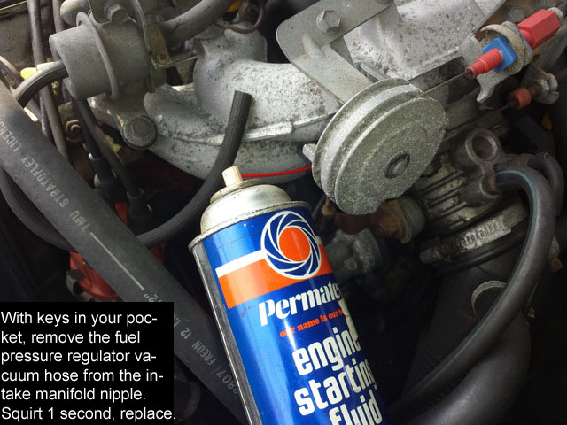
I suggest you make sure the cam is turning when you crank. Then squirt something flammable into the manifold where the vacuum line goes in from the fuel pressure regulator. See if it catches for a moment then. That's a good way to verify spark.
--
Art Benstein near Baltimore
4 out of 3 people struggle with math.
|
|
|
|
|
Hi Art. You're suggesting the OP's original sensor may be okay when seeing the 180 ohms through the sensor coil (pins 1-2)? The OP of course needs to check the integrity of the foil shield on pin 3 to chassis ground, both visually and electrically.
My understanding, and I'm sure you'll correct me if I'm off base here, is that the waveform of the CPS signal is very sensitive to interference. The spiral wrap aluminum foil is the shield and needs to be grounded at both ends to the chassis, otherwise the open segments not only permit intereference at the damaged location, they become antennas (okay, antennae) creating interference all along the cable that more easily disrupts the purity of the waveform. The foil commonly fails at the flex point where the cable goes into the sensor, part way up scuffing against things like dispstick tubes and cooling system plumbing, or at any sharp bends in the cable routing. This is often evidenced by damage to the insulation, but not always. The foil doesn't have to be damaged all the way around to become a problem as it's a spiral.
FYI to others, there are two standoffs (plastic clips), attached to things like the dipstic tubes and waterpump return line, used to minimize cable flexing and bending from the engine rocking around, but these often break or go missing. I make my own standoffs out of quality large black zip ties looped through a segment of vinyl tubing that usually last a couple of years. In damaged areas, some people report success baring back a little bit of insulation and wrapping with aluminum foil to restore the shield, but at that stage I always opt for a new sensor.
When the sensors fail they often start misbehaving before there's a no start. Questions to you Art, when the sensor coils fail, do they just tend to get weaker, or do they tend to become increasingly intermittent, like under temparature change? In my experience the OBD system does not necessarily report a missing signal, and when it does it's often the code for a missing signal being passed from ignition controller to the fuel ECU (1-3-1 on socket 2) suggestig a weak signal, rather than from the sensor to the ignition controller (2-1-4 on socket 6) suggesting a failed sensor coil or broken wire. That suggests to me that a failed shield would be the issue in those cases. Also in my experience, failing sensors seem to first start misbehaving at a warm start. Comments?
Genuine Volvo sensors will of course be the most reliable, but aren't overly cheap. A variety of aftermarket sensors are available for considerably less and I've always had good luck with the ones sold by the more reputable parts houses. There are ones being sold out of China for as little as $5-$10 with free shipping, but I have no intention of wasting even that little amount to see if they're any good or would last more than 5 minutes.
--
Dave -still with 940's, prev 740/240/140/120 You'd think I'd have learned by now
|
|
|
|
|
"The OP of course needs to check the integrity of the foil shield on pin 3 to chassis ground, both visually and electrically."
I wonder how you would suggest he does this??
Recall, we're talking about measuring resistance of the sensor in this thread; that's why I had OP clarify the question. The sensor's wiring includes a shield of course, all the way from the reluctor head to its electrical plug. It is made from a bare stranded drain wire in contact with the foil wrap with no connection at the sensor end.
Maybe you're thinking of testing the wiring harness back to the ICU?
"In damaged areas, some people report success baring back a little bit of insulation and wrapping with aluminum foil to restore the shield, but at that stage I always opt for a new sensor."
"Some people" got lucky and think that is what led them to report success. More likely the harness connector had a pin push back during the replacement. The problem with the broken sheathing is that it allows water to follow the wiring into the sensor body (no drip loop here) and eventually that magnet core rusts the unit swells and locks itself into the fragile aluminum bracket. Yes, good idea to opt for a new sensor before that occurs.
"Genuine Volvo sensors will of course be the most reliable, but aren't overly cheap. A variety of aftermarket sensors are available for considerably less and I've always had good luck with the ones sold by the more reputable parts houses. There are ones being sold out of China for as little as $5-$10 with free shipping, but I have no intention of wasting even that little amount to see if they're any good or would last more than 5 minutes."
How would you know a sensor from the Volvo dealer is any different from the $12 sensors I use? You imagine Volvo (GCP) is doing incoming inspection on parts not made in production quantities for 30 years? Could be this is misplaced faith.
I believe these sensors are difficult to make, and make reliable, due to the fine magnet wire and the physics of encapsulation. If Electricfil/Bougicord was the OEM for this part, do you imagine they are still being made in France and enjoying life-cycle burn-in after potting. I don't.
My guess is they are tested once after being built. And I'd venture a goodly percentage of built sensors fail right then. I think we owners of antiques and the vendor's money-back warranties are the only quality assurance measures. And why not sell them out of China where they are made? All of them on the same line, I bet, as I cannot by visual inspection distinguish them from a 20-year-old Bougicord NOS given to me.
--
Art Benstein near Baltimore
I thought growing old would take longer.
|
|
|
|
|
Based on the green wiring diagrams, I'd always thought the shield was connected to ground at both ends of its run and could be checked for continuity between connector pin 3 and the metal sleeve in the bolt mounting hole, but it appears you're right. Coaxial shields do need to be tied to ground at both ends to maximize protection against interference, so that made sense. The Volvo green wiring manuals (eg. EZ 116K) even show the shield tied to a black ground wire that runs all the down the cable and connected to the sensor head, which I assumed was tied to the mounting bolt hole. I've only ever tested bad ones from that bolt hole and not getting continuity always assumed their ground shield was broken, hence why they were bad. I just now tested a new one I have in stock and what do you know, that metal bolt sleeve isn't an electrical ground, just structural support.
I agree with your comments about Chinese manufacture, but I'm always concerned the quality control in the ones I might get direct from an unknown Chinese distributor would be less than the quality control the likes of Volvo would insist on. With modern production methods and these sensors likely costing barely a dollar to manufacture in quantity, there may be no reason to have varying levels of quality control. The vast majority of the cost is in the engineering, packaging, shipping, warehousing, marketing, distribution and technical support, which is why we pay a premium for Volvo to keep their branded boxes in their parts chain. The worst case I used to imagine was the rejects in the waste bin at the end of the production line would be the ones sold to me for that $5. In reality, they're quite possibly selling good quality excess production for dirt cheap, or using the same guts, but in a different plastic mold done on a secondary production line. Some Western manufacturers insist on their injection molds being kept under secure conditions and returned to the engineers so as to protect their brand and patents. You've now got me curious and interested in getting a dirt cheap one just to look at it and try out, of course packing the brand new good one I have as a spare.
--
Dave -still with 940's, prev 740/240/140/120 You'd think I'd have learned by now
|
|
|
|
|
I see what you mean in the EZK foldout in the WDM. In the symbols the draftsperson chose to represent the signals at the ICU it implies a differential input. But even so, the shield should never be returned to ground at both ends of a low-level line like this one. My experience in the field would have me wagering you could de-pin #3 in the CPS jack and never see a difference in performance. The circuit is actually not differential, but single ended.
Look at figure 7 here: https://www.analog.com/media/en/technical-documentation/application-notes/41727248an_347.pdf
Have to laugh at the notion someone would be shipping us sensors from the waste bin or selling them to resellers like Walker. It is pretty desperate to be counterfeiting such an arcane piece of merchandise. Someone would have learned by now.
--
Art Benstein near Baltimore
A little gray hair is a small price to pay for all this wisdom!
|
|
|
|
|
Interesting article. Some of that is beyond my pay grade, especially as it's been so many years since I was around electrical engineers, but I got a definite chuckle out of:
From the outset, it should be noted that shielding problems are always rational and do not involve the occult, but they are not always straightforward.
Reading elsewhere about shielding, the story is not at all simple and some of the reasoning is all over the map. I get why the author said that.
--
Dave -still with 940's, prev 740/240/140/120 You'd think I'd have learned by now
|
|
|
|
|