|
|
|
Hello to all. Taking a trip across the little state of Delaware this morning my speedometer showed no sign of life. Ditto also on the trip register. However the
rpm tach was just fine. I checked the speedometer repair section and looks like my
problem may be similiar to what the 91-92 yazaki speedometers are experiencing. Since my rpm's are ok the rear sensor from differential must be ok. Problem is most likely on circuit board, bad caps, chip , etc. Will the 940 93's suffer the same problems as the 91-92 700's? If so, then I will follow the repair instructions. Any insight or suggestion most welcomed.
|
|
|
|
|
Hello to all. Finally found the problem with my 940 Speedo.
Many thanks to Art for providing me with so much needed
information. Also to Spook and others who had input. Both the
sensor in the differential and the wiring leading to the speedo
were ok. The sensor reading was measured at 1.35k ohms (provided for
future reference). Removal of the speedometer assembly was straightforward.
The FAQ regarding removal of this assembly was invaluable. A number of
screws to remove the backplate and to expose the speedometer itself.
A close examination of the circuit board showed that melting/leakage had
occurred on the solder side of the board and some of the copper trace
had been dissolved. All the electrolytic Capacitors were ok, no indication
whatsoever of leakage. I measured all capacitors and all were within
capacitance spec's. This does not account for possible DC leakage due
to the ageing process of the dielectric. I did not change any Capacitors.
Regarding the board, the copper trace disappeared when under and next to
diode ZD1. I had to lift the diode in-order to clean the board of whatever
had melted onto it. Denatured alcohol did a fair job.
Continuity checks affirmed that an open had occurred.
A jumper wire soldered in parallel with the broken trace took
care of bringing the speedo back to life. Just my opinion of what may have happened;
I believe the blackened coating of whatever was on that portion of the
board may have come from the heat generated by diode ZD1 and/or D1. Either the plastic, or the coating of the diode melted onto that area of the board. The chemical contained in the coating probably caustic to copper. The slow process of eating away at the trace area began. It may have taken years to eat away at the copper trace which does not have any thickness to speak of. Art had sent me an example of a 93 speedometer board which had been repaired and contained pictures of where the boards copper traces were suppose to be. A great help.
Re-installing was a snap, and the test drive confirmed the speedo "back on line".
I want to mention some advice regarding the various caps on the 93-94
speedometer boards. These caps can be changed out without removing the speedometer circuit board from the speedometer. The caps that should be
swapped out are on or near the outside corners of the board and are within reach of either your fingers or needle nose pliers. I will change mine out later in the year, time permitting .Use temp rated 105c, not the 85c.
Somehow I hope this short experience helps someone. pic uploaded.

|
|
|
|
|
Similar findings on my 94 board but my speedo still operates. It was an accidental finding as I meant to repair the clock instead (its magnetic motor had broken). In my case one of the legs (terminal wire) of the speedo's capacitor had melted away (open circuit) with some corrosion on the circuit traces around it. Surely the corroding agent must had been electrolyte from that capacitor. Cleaned the traces with some alcohol and replaced the capacitor with another from my parts bin. Hard wired the corroded traces with some unused component legs and it was all ok. Caught before the act.
Amarin.
|
|
|
|
|
Timely post... I just had my 94 940 speedometer/odometer quit.
Is the 94 speedo the same as the 93?
For speedo repair, would any capacitors need to be replaced?
The "cleanflametrap" article mentions only cleaning.
Thanks.
|
|
|
|
|
Dear MrNabisco,
Hope you're well. Check the wiring connector to the sensor at the top of the differential housing. If the wires are corroded and/or broken, that explains why the speedometer no longer shows speed or mileage.
If those wires are in perfect condition - highly unlikely - use an ohm-meter to see if there's continuity at the instrument cluster speedometer connector. If so - if the sensor's wires are unbroken - then the problem is the speedometer unit itself.
The 1993 and 1994 speedometers are identical, so far as I know.
Hope this helps.
Yours faithfully,
Spook
|
|
|
|
|
Thanks for the tip Spook.
Went out and found the sensor wires totally disconnected. So there...
Must be corrosion from being parked outside for 25 years.
Very happy I don't need to try and rebuild a speedo.
Got the connector from the eBay link Amarin provided. $26 seems pricey, but when you need a part you need a part.
Thanks to all who posted. This was a timely and helpful thread for me.
|
|
|
|
|
Check your wiring at the diff end. Need to go underneath at the back of the car unfortunately.
Here's an example:
https://www.ebay.com/itm/VOLVO-240-245-740-745-speedometer-differential-sensor-connector-harness-kit/362426768390?hash=item5462519c06:g:FuQAAOSwMudbiwIG
There's a complete Volvo harness kit replacing the wiring from diff to the small black box (match box size) in the trunk but I can't seem to find it. The partial harness above is also sufficient to use but you need to splice it in. Polarity doesn't matter.
Amarin.
|
|
|
|
|
Hey Amarin, wiring is ok. Connector plug disconnected from sensor without any issues and wiring is in good shape. Probably because the car had always been garaged. Have to find out what a good resistance reading should be when measuring the sensor.
|
|
|
|
|
Seeing that the speedometer and odometer are both inoperative would suggest to me that the signal is not reaching the cluster.
The connector to the differential sensor lives in a harsh environment and after 25 years I have found many of them to be in poor condition. I recently had to change out the one on my son's 940 wagon after repairing it with a wire splice several years ago.
If you need to replace the connector you will find it to be same type that is used in supplying power to the window washer motor.
Randy
|
|
|
|
|
Thanks Randy. I found that the connector, even after 25 years, was still in acceptable condition. The wiring from the sensor up to the connector in the
"black Box" was in good shape (it rang out ok). Even the connector disconnected
from the sensor easily, just a light tug. I measured the sensor itself at 1.35k
ohms. Cannot find what it should read, if anything. I made an attempt to pull
the sensor away from the differential and although it would swivel, it just refused to be yanked off of its mounting. Appreciate your input.
|
|

|
|
Can't tell you the trouble isn't in the cluster, but also be advised the sender on the differential does not provide the signal to the tachometer that counts your engine's revs. That signal is generated by the ignition system. So, you still ought to have a look under the car at the wires going to the differential sender.
Notes on 740/940 Volvo Speedometers
--
Art Benstein near Baltimore
"Never trust the work of the last guy, even if you're the last guy"
|
|
|
|
|
Thank you Art for info. I will check the sensor coming off the differential. I
believe I read in the repair section running some wires off of the sensor and shorting them together for 4-5 times per sec for a read of 15mph on the speedo. I will try that first before digging into the mess behind the dash.
Appreciate the notes, especially regarding the 93 Yazaki speedometer. The schematic will come in handy, hopefully not needed!! Oh how easy it was to change that simple failed gear in the 240's speedometer. With progress comes complexity,
and perhaps a bit of over-engineering. Let's see how it goes.
|
|
|
|
|
Dear Dom's940,
Hope you're well. To ease removal of the wiring connector from the speedo sensor mounted in the differential cover, apply lots of PB Blaster or other penetrating oil. The oil, given time, will weaken the corrosion bond between the wiring harness connector's metal sleeves, and the sensor's metal pins.
Once the oil has had time to work, cut any remaining wires. The sensor's connector can then be turned, so it points down-ward (towards the ground). That will ease further work.
You may then be able to pull the wiring harness connector free from the sensor by GENTLY tugging on the wiring harness connector's housing. I emphasize gently, as replacing the sensor itself (Volvo #1398321) will cost about $180 at a U.S.-based Volvo dealer.
If the wiring harness connector won't budge - as is likely - use a pliers carefully to break the wiring harness connector's housing, to expose the wiring harness connector's sleeves. Use a needle-nosed pliers to try to turn the sleeves, and so to separate them from the sensor's pins. Do not damage the sensor's wiring connector housing!
Once the sleeves have been removed, clean the sensor's round pins using fine sandpaper and coat the pins with di-electric grease. Then, side onto the wiring harness short lengths of heat-shrink tubing. These lengths should suffice to cover each splice in the wires.
Then splice onto the wiring harness, a compatible two-wire connector. I'd solder the twisted-together wires using a rosin-core solder. Once the wires have been soldered, slide the heat shrink tubing over the soldered joints and shrink the turbing using a hair-dryer of an industrial heat gun on "low".
I'd then wrap both spliced wires with butyl rubber tape. Butyl rubber tape - used to waterproof windshields - is very sticky and remains flexible. Most other water-proofing materials harden with time, crack, and so fail. You should be able to get butyl rubber tape at an auto glass supply house.
I'd wrap the wiring harness connector and the top of the sensor housing with butyl rubber tape. Compressing the tape with your fingers will form it into a "boot". This "boot" will keep water from corroding the connectors.
A dollar's worth of butyl rubber tape that encases completely the sensor's wiring connector will help to ensure you do not need to repeat this job anytime soon.
Hope this helps.
Yours faithfully,
Spook
|
|
|
|
|
Hey Spook, following ur directions. The connector came off easily and wiring was in good condition. cleaned the contacts and reinstalled. Also measured the resistance of the sensor from the end of the sensor harness and measured 1.35k ohms. Unsure as to what it should accurately read but at least its not a short.
|
|
|
|
|
had a chance to get back to the speedometer problem this afternoon. The
plug came off of the Sensor/sender easily. The wires looked very good for
\the age of the car (car had always been garaged). applied a dvm to wires
to check for continuity. Wires ok from sensor to the black box located
on the left side of the wagon (close to the antenna mast motor assembly).
The black box has the sensor wire mated to wiring running forward to the speedometer. Volvo provided an easy way to change out a defective sensor wire
instead of running a new wire from the sensor all the way forward. Thoughtful?
I attempted to remove the sensor, but it would not budge. Decided to leave it
alone. Cleaned the sensor pins with QC contact cleaner and reinstalled plug.
Took an ohm meter check of the sensor and it did read 1.35k ohms. Have not been
able to find what the correct reading on the sensor should read. I suppose next would be to check the wiring running from that black box to the speedo.
That will mean cracking open the dashboard. The was pretty simple on the 240, not sure about the 940. So, thats where I am for now. Many thanks to all, Art, that schematic will be of assistance if I have to dig that far. Thank you spook and others for all the info.
|
|
|
|
|
I agree with Randy's advice as a start.
I don't agree with the advice to hang a long wire on the plug, shorting it repeatedly, to simulate a signal. Though I can picture a situation where this may have actually worked (high electrical noise environment under fluorescent lamps perhaps) the signal both the Yazaki and VDO clusters are looking for is generated voltage, not switch closure. If it does work for you, that's OK to focus suspicion on the sender, but if it doesn't cause indication on the speedometer, don't assume that vindicates the sender.
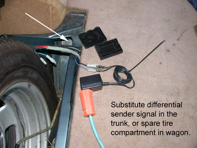
A better test is substituting a signal, or just confirming the resistance of the sender can be seen from the cluster looking back, but I suspect most issues will be obvious and look like this example from a 240:


--
Art Benstein near Baltimore
"...people will always choose a simple lie over a complicated truth, because the lie has one unbeatable advantage: the truth always has to stick to what actually happened, whereas the lie just has to be easy to believe" - Fredrik Backman
|
|
|
|
|
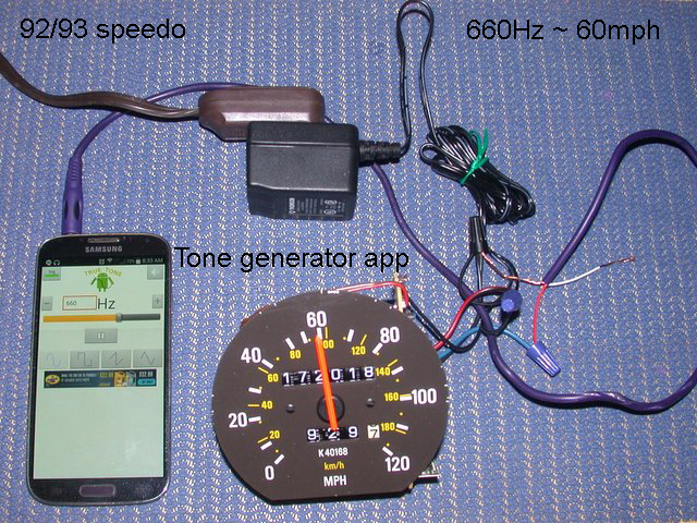
Art, just a brief question. You had mentioned substituting a signal in your response to my problem. Examining the schematic leads me to believe that I can
inject a 1 volt/1khz sine wave signal from the "black box" (contains the connector joining the sensor harness to the speedometer wiring) to the speedometer and perhaps see a response . I have a signal generator and there seems to be no issues with polarities. By the way, the wiring and connector rang out good. Any thoughts??
|
|
|
|
|
Great idea with the cellphone, never knew there was a tone generator app.
What will they think of next. I was not sure of how much signal voltage to
apply to the speedometer circuit but you are using an a/c xformer which is
rated at what voltage 5/9/12?? I have a variable voltage xformer so will start
at the lowest. Must check the schematic again.
|
|
|
|
|
Let me post the link again, because some answers to the transformer voltage question and the sender's resistance question were given. Caveat: The transformer being 9V suggested is way more than either circuit needs, but I only know for certain the VDO input shaper will deal with it -- haven't tried it on a 940. Don't own a 940. Feel sorry for y'all with that capacitor mess. :) At least it is a lot easier to deal with on the 93/94 Yazaki single-sided board than on the 91/92.
http://cleanflametrap.com/speedoDiag.html
--
Art Benstein near Baltimore
It's all fun and games until your jeans don't fit.
|
|
|
|
|