|
|
|
Hi, all.
This is about the retaining springs on the Girling front calipers' pads, and is meant mainly for newbies trying to follow Bentley's manual.
I've been doing brake jobs on my cars for decades (literally), and yet I just now discovered a mistake* in my Bentley (for the record, my edition has a 1993 copyright date -- noted here in case there are other editions in which this has been corrected).
[ * a mistake or perhaps just a discrepancy -- I don't know serious a difference this is.]
For all these decades (I've owned Volvos since 1973, with that year's 164), I've always relied mainly on my Volvo-published, "Green" shop manuals (I have several editions, since my cars span from then to 1993). But now and then I also refer to my Bentley for the "simpler" version, especially when the Green manual calls for a certain official tool, and Bentley says "pry it with a screwdriver or pliers", if you know what I mean :-).
Anyway, I've always installed my pads the way the Green books describes and illustrates doing so. But I happened to scan the Bentley, and for the first time my eye, seeing a few illustrations, noticed a discrepancy with the illustrations (and the way I always did my pads) in my Green manuals.
In the Green manuals, the main holding springs (not the little retaining clips) are installed with the main portion inboard of the pads' backing plate, and the U-shaped portion that fits over the edge of the plate and shim extending outward.
In contrast, the Bentley's photos, Fig. 4 on pg 500-4, Fig. 2 on pg 510-2, and Fig. 4 on pg 510-3, all clearly show these springs mounted outboard, and the U-shaped piece extending inward, the exact opposite of the Green manuals. Curiously, however, Fig. 3 on pg 510-2 shows the springs mounted differently (i.e., the same way as the Green manuals).
I would, in fact, recommend the Green manuals' way, because from my experience, when installing new, full-thickness pads there is only enough room for the retaining clips -- and trying to mount the springs per the Bentley photo's way in that limited space must really create a difficult situation.
I hope this saved someone some hassle.
Regards.
|
|
posted by
someone claiming to be wolfi
on
Mon Jan 17 05:25 CST 2005 [ RELATED]
|
|
VW/Audi had a few reverse-wired cold start temperature relays in early 80s.. This affected proper diagnosis for years and probably some are still out there, uncorrected. Were any of these Bosch relays reverse-installed in Volvo engines? My 82 LH is OK, my 85 Audi wasn't. The relay itself was OK but wire to heating element and power wire from relay were reversed in wire harness. This resulted in at least one Mitchel wiring diagram being screwed up. A problem in Chilton's manuals is the interchangeable, indiscriminate and sometimes wrong and always confusing reference to the CIS (the K-Jet) versus the CI system versus the Ignition system.. I don't believe Chilton has ever gotten that sorted out properly.
|
|
|
|
|
Yes, the spring would seem to belong on the inside. As opposed to the revered Bentley manual, you'll be happy to note that my Haynes and Chilton's seem to have it right, same as your Volvo green manual, although for my Chilton's you pretty much need a microscope to see it.
In actuallity, I doubt it matters a huge amount which way they go, but if you think it through logically, one way is designed to be better and that's on the inside as the Volvo manual shows. Note that these are called anti-rattle springs. As far as rattling around in the vertical plane, it hardly matters which side of the pad they're on. But as for the horizontal plane, one way is slightly better than the other, although the difference is probably about 15% as far as horizontal freedom to rattle is concerned. Correct orientation will have virtually no effect on braking and perhaps a tiny effect on pad wear.
As a bit of background, we all know when you take your foot off the brake the piston retracts a small amount to release the pad. The piston seal deforms out under braking pressure (deformation is also accentuated by the cross-section design of the seal and seat). When pressure is released the seal returns to its undeformed state, dragging the piston back with it. If this didn't happen the residual brake pressure would leave the pads scuffing against the rotor, increasing pad wear and adding brake heat.
The anti-rattle spring, when properly positioned on the inside, tends to keep the pad lightly pushed back against the retracted piston. When mounted the "wrong" way this doesn't happen. That's not a huge crime, the design of the spring in extension would push the pad less against the rotor than it would against the piston in compression -hardly enough to cause any serious wear. The pad would just have a little more freedom to move horizontally. The added amount of audible rattle and brake pad wear when this happens is probably miniscule if not negligible, but nonetheless one way is definitely designed to be better than the other. So the severity of Bentley's crime is pretty small in my opinion.
Here's how the spring works. If you carefully look at the photo in Art's post you'll see that the ends of the spring rest slightly away from the pad backing. That's because the middle pad clip is offset outward from the ends. When out of the caliper the spring itself is actually pretty flat. The offset happens as a result of the design of the spring when the ends are pushed back behind the slide pins. If you lay one of these springs on a flat surface and pinch in the ends you'll see why this is so compared to when you pinch it flipped over. Simple, but effective -a sign of engineering genius. Looking at it edge-on as in the photo, the middle (clip) part of the spring gets pushed in during braking then pushes the pad back out when released -it's really not much force, just enough to pursuade it from going the other way. As the pad wears, the ends of the spring slide in along the pins to keep the process aligned. If the pins are particularly rough this may not happen smoothly -so clean them at each pad change.
And, yes, I've put them in the wrong way more than once on my life.
--
Dave -own 940's, prev 740/240/140/120 & quasi-expert only on a good day
|
|

|
|
My! What sharp eyes you have! I never noticed that one in some 13 years. Of course, after a couple of pad changes that section doesn't get much play. Wonder if the "wrong" way poses a problem.
Although it has some errors, IMO the Bentley manual is still the one to have (after green books). My Bentley is dog-eared from 13 years of use. The Haynes is like new.
Here are the Bentley errors I've recorded so far (more marked-up in later sections).
PAGE #
032-7 — Fig. B10106, Fuel Pump/Filter misidentified
214-2 — Fig. 3. Shows front of camshaft. Text refers to "rubber plug" which is at the Rear.
214-4 — Three erroneous Cautions about valve-to-piston interference.
214-5 — One erroneous valve/piston caution.
........
215-4 — Step 9 text ("pull") disagrees with Fig. 9 caption ("push").
215-5 — Step 7. "See Fig. 11" should conclude Step 6 (reference to guide plate).
215-5 — Tightening Torque stage 2 should be 60° (not 90°)
215-5 — Fig. 11 Camshaft sprocket should be Crankshaft
.........
216-9 — B230 crank pulley Tightening Torque missing (Stage 1 - 44 ft. lb., Stage 2 - 60°)
.........
220-5 — "Oil Pressure Warning System" No Oil Pressure info in "380 Instruments" , as referenced.
.........
240-18 — "to test start injector" Step 2 says to disable ignition "as described in (Chapter 280). But with no ignition, there will be no Fuel operation as needed in Step 5 to test the Cold Start Injector operation.
.........
240-21 — Can't adjust dwell (Step 5) with O2 sensor disconnected (Step 4)
--
Bruce Young
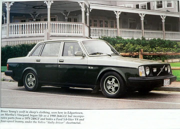
'93 940-NA (current) — 240s (one V8) — 140s — 122s — since '63.
|
|
|
|
|
I have found other mistakes in Beltley as well. I recall one involving the timing belt replacement - the amount to tighten the crankshaft. There are others I don't recall off the top of my head.
-Ted
|
|
|
|
|
Ken;
I think this applies to my car as well (Girlings on the front)
Saved anyhow for future ref. Thanks.
--
Norm Cook Vancouver BC; 1989 745T 200,000KM
|
|

|
|
No kidding!
As most of the drawings and text in Bentley seem to be lifted straight from Volvo's manuals, I just had to take a closer look-- at the photos.
The format of Bentley's photos (brake section) looks identical, down to the placement of the number IDs. Even the brake fluid bottle and bleed tube pictures have the same look, but-- not identical!
Even though your observant discovery points out a flaw and has me looking for that red pen again, I give Bentley's publication more credit than I previously had, believing it to be mainly an abridgement of the green books.
Now, I just have to dig up something to see how I've been placing the spring, as my usual concern when doing so is getting the tongue in the middle over the shim when I forget to snip out a notch first.

--
Art Benstein near Baltimore Crrrrazy Ray's!
|
|

|
|
Art, have you compiled a list of the discrepancies you've noticed in Bentley? You've mentioned the red pen before and I'd be curious to know which pages need revision.
--
'80 DL 2 dr
|
|

|
|
Sorry, it was in my case a figure of speech. I once had a job requiring regular review of a manufacturer's tech pubs output, so I gladly set aside and lost my red pen after that was over. I've unofficially designated Lucid as my keeper of the Bentley errata sheet.
By the way, there's no end to green book gaffs either, some harmless but rather humorous like the description for item A on this page about Radio wiring.
--
Art Benstein near Baltimore Crrrrazy Ray's!
|
|
|
|
|
Thanks for the tip.
--
Thanks everyone for the advice. 81 242 Brick Off Blocks, Turbo bars and wheels, B21F, M46; 86 244, B230, 148k , auto.
|
|
|
|
|


