|
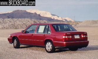
I documented the R&R of the PNP Sensor on our 1998 S90 this weekend. I'll be doing this procedure again in the next couple of weeks on our 1995 960 so I got a little carried away with the level of detail in the procedue so just read it with a grain of salt.
It looks better in the MS Word doc I created it in. Contact me via e-mail if you want a copy of that doc.
------------------------------------------------------------------------------
Volvo 960/S90 PNP Switch Removal & Replacement Procedure
A.) Removal
1. Raise the front of the car, Ramps are preferable.
2. Chock wheels and put transmission in Neutral.
3. Apply rust penetrant (i.e. Gibbs) to the six (4 front, 2 rear)14 mm exhaust pipe nuts.
4. Remove three 10 mm bolts that hold on the O2 Sensor wiring to the trans. cross member.
5. Remove one 10 mm nut and three plastic wire retainers for O2 Sensors on frame above Cat. Conv.
6. Loosen all six 14mm exhaust nuts, drop the rear of the pipe. Remove 3 of the 4 front 14 mm nuts so that 1 nut is still holding the pipes up. Pipe should swing from side to side to make clearance to the PNP switch.
7. Remove two 10 mm nuts & fender washers holding heat shield above Cat. Conv. on
8. Disconnect 17 mm trans. cooler return line on transmission
9. Allow trans fluid to drain from fitting before continuing (approx. 1.5 quarts). Drains slowly, will take about 1/2 hour.
10. Remove 12mm bolt from top of PNP switch. Caution : it is easy to round this nut. It has a small head and is soft. Use a six point socket and take it slow.
11. Pry 4 metal retaining fingers away from 22 mm nut on PNP Switch shaft.
12. Remove 22 mm nut on PNP switch.
13. Evenly pull PNP switch off trans shaft.
14. Cut cable tie above PNP switch on the wiring harness.
15. Clip the remaining three cable ties and loosen the metal retainer on the drivers side of the transmission holding the PNP switch wiring harness
16. The PNP Switch wiring harness is the middle of three wiring connectors attached to the front of the transmission on the driverís side.
17. Slide the middle connector approx. 3/8 inch forward. This will release the connector from the mounting bracket making it easier to separate the two ends.
18. Grip the connectors with both hands ensuring you are squeezing the clips on each side of the connector to release it while pulling the two pieces apart. They are in very tight and will require some force to separate. I had to spray the connector with penentrant to help loosen it.
19. You can now pull the PNP switch out from either side of the transmission.
B.) Replacement
1. Install new PNP Switch over the slotted trans shaft and feed wiring harness over the top of the trans to the driverís side.
2. (Optional) Add a rubber (neoprene) washer to the 12 mm bold between the PNP switch and the washer so that the bolt wonít have to be installed too tight and the switch wonít rotate after adjustment. The bolt is soft and has a small head and can easily be stripped so be careful.
3. Add a drop of blue (medium strength) lock-tite to the end of this 12 mm bolt before installing and securing the PNP switch.
4. Install securing washer with 4 small fingers over the slotted shaft and secure with 22 mm nut. Torque to 5 ft. lbs., then bend the fingers over the nut so it canít back off.
5. Adjust PNP switch in one of three ways in order of preference:
a. Use tool 9995475 and align PNP switch such that the fine line is visible thru the slot in the tool. Then tighten 12mm bolt (torque unknown, but it does not need to be too tight because of the rubber washer).
b. Turn ignition on (do not start), put Transmission in Reverse and rotate the PNP switch until the backup lights come on. Rotate switch until the back up lights go back out and center the switch. Then tighten 12mm bolt (torque unknown, but it does not need to be too tight because of the rubber washer).
c. Line up PNP switch such that the indicator line on the switch is vertical and parallel with the slotted trans. shaft (with the trans. In Neutral). Then tighten 12mm bolt (torque unknown, but it does not need to be too tight because of the rubber washer).
6. Add a new wire tie above the PNP switch replacing the on removed earlier. (optional)
7. Reconnect trans. Cooler return line.
8. Install Cat. Conv. heat shield with two 10 mm nuts and fender washers
9. Reconnect exhaust pipes, torque 14 mm flange bolts to 30 ft. lbs, and bolts at the rear of the cat. To 18 ft.lbs.
10. Re-attach one 10 mm nut and three plastic wire retainers for the O2 sensors to the chassis.
11. Re-attach the three 10 mm bolts holding the wiring harness for the O2 sensors to the transmission cross member
12. Plug the new connector to the wiring harness and slide the connector back onto the bracket.
13. Add new wire ties where appropriate to keep wires from chaffing, being sure the new wiring harness is in the metal clip as well.
14. Check all connections for leaks and/or chaffing.
15. Add new ATF fluid to makeup for amount lost. (approx. 1.5 quarts)
16. Start vehicle, check for exhaust and transmission fluid leaks.
17. Back car off of ramps or remove from stands and test drive the car thru all ranges L, 3, D, N, R, P.
--
1998 S90 062,925 1995 964 145,750
|

