|
|
|
I rewired the 30 amp fuse holder for the main relay due to melt down. Today my main dual relay melted part of the relay socket. Had to pull the whole fuse/relay tray out and install another relay. Question is what and why is the power draw so much and the 30 amp fuse was fine and just warm. I'm checking the wiring to both pumps and ground wires. Main pump is new with low mileage and the intank pump is about 3/months old. Any Ideals about the causes of the circuit overheating. Care runs smoothly until things heat up in the relays.
|
|
-
|
|
|
Turns out that the fuel pump was slowly, without Audible noise, started getting faulty. First the pump relay fuse socket was in bad shape so I rewire a heavy duty marine fuse holder. Ran much better for a few weeks but, still have power drop in acceleration. The last thing that happened was the main relay socket overheated. Finally decided with the overheating of the electrical for the pump relay, it must be the pump. Just replaced it with the same aftermarket brand pump and the car runs so smooth now. Hopefully everything is fine now. 25 amp fuse is back in place and No excessively warm relay or fuse.....No OBDII diagnostic on these cars. I should have realized the overheating was the pump going bad....No specifications On amperage load for the pump or I would have tested.the power draw. Anyway......I'm up and running smoothly. Thanks all that replied. 🎯
|
|
-
|
|
|
The main fuel pump is fused at 15 Amps by Fuse 11 all by itself in LH 2.4 .
You might try testing the old fuel pump current draw to see how much it was.
If F-11 didn't blow, maybe the other aux. pump on Fuse 1 is drawing too much current to start frying your distribution board and relay socket.
Bill
|
|
-
|
|
|
I'm wondering if the OP may have misidentified the fuse. If a 30 amp fuse is blowing, it could be fuse #6 (heated seats), #8 (power windows), #10 (heated rear window, power sunroof, power mirrors) or #16 (heater fan).
Now if someone put a 30 amp fuse in the #11 fuse socket then that might suggest a PO may have had problems with the original 15 amp fuse blowing too easily from something like a badly worn pump, especially if it spent much of its life running without the help of the in-tank pre-pump. More than likely the fuse blew and there was no spare 15 amp in the side slots so the PO just used whatever spare was available. If fuse #11 is readily blowing, it could also be a damaged wire, like near the top of the tank fuel sending unit, shorting to the body.
Just FYI, 1989 was a transition year in the North American market. Most 740 B230FT still had LH 2.2, while the NA B230F and 16-valve B234F got the new LH 2.4. All used fuse #11 for the fuel pumps.
--
Dave -still with 940's, prev 740/240/140/120 You'd think I'd have learned by now
|
|
-
|
|
|
Hi Dave,
Natanha can do a voltage drop test of Fuse 1 and Fuse 11
with his DC Milliameter to determine how much current is flowing in both circuits.
He might test his old pump and see what it is drawing.
It might be that fuel pumps draw more current as they get ready to fail.
Fuse Voltage Drop Conversion Chart (partial)
Select the correct chart for the fuse being tested:
Mini Fuses
Maxi Fuses
Standard ATC (ATO) Fuses Volvo 740/940/850
Cartridge Fuses
Find the column matching the amp reading being tested
Find the row matching millivolt number (that matches your meter reading)
Where the row and column intersect is the circuits current draw in milliamps
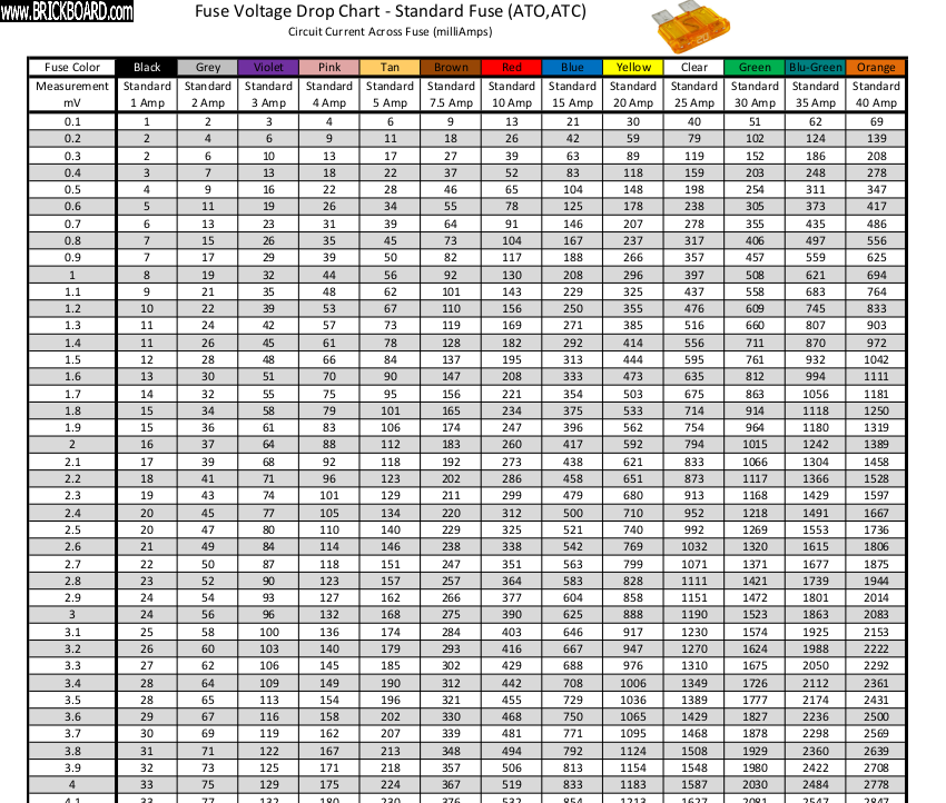
Convert millivolt readings into a milliamp number that represents the current flowing through a fuse.
For readings above 10 mV multiply X 10 (see example)
Move the decimal point 3 to the left to convert mV to Amps.
In my 1993 940T I measured F1 & F11.
Fuse 1 26 mV voltage drop 25 Amp ATC fuse
I used 2.6 mV on the chart that goes up to 10 Mv then multiply by 10
2.6 = 1032 mV or 1.032 Amps
X10 = 10.32 Amps for F1 Main fuel fuse.
Powered from Fuse 1:
Main fuel relay coil
Fuel and Ignition ECUs
Both fuel pumps
PTC resistor
MAF sensor
RSR coil
Total for Fuse 1 = 10.32 Amps
Fuse-11 In Tank primer pump 6/33 only: 16 mV 15 Amp fuse = 5.42 Amps
Video here: ( good to track battery killer lights on in the glovebox etc.)
https://m.roadkillcustoms.com/how-to-perform-a-parasitic-draw-test/
Complete chart here for ATC/ATO fuses 0-10 mV:
https://m.roadkillcustoms.com/wp-content/technical-pdf/Standard%20ATC%20Fuse%20Voltage%20Drop%20Chart.pdf
Other style fuse charts available.
There's some other handy tech stuff at this nice website.
Cheers, Bill
|
|
-
|
|
|
Replaced the old pump with new. Car runs better than ever now. Problem is I'm still getting relay overheating. 25amp fuse is looking fine since I by-pass the fuse holder and installed a marine grade fuse holder. Would the ECU computer cause a power circuit draw ? Starting to think of installing a separate heavy duty relay . Seems the only available relays are cheaply made.
|
|
-
|
|
|
Stop throwing parts.
Start by measuring current flow with the engine running in Fuse 1 and Fuse 11 circuits.
That will help point to the cause of your problem.
Post back.
Bill
|
|
-
|
|
|
BB...The fuel pump was on it's way out. Intermediate Buzzing and a new pump fixed drivability problems. I think it's the cheaply made relays.
|
|
-
|
|
|
Why can't you measure fuse circuit current ?
I just posted three different ways for you.
I'd like to know what your "bad" in-tank pump was drawing.
My car runs without the in-tank pump (with a full gas tank)
I measured current draw of fuse 11 @ 3.6 amps.
Fuse 11 for the in-tank pump is fused all by itself by a 15 Amp fuse.
Fuse 11 gets it's 12 volts from Fuse 1 a 25 amp fuse.
Fuse 1 current draw in my car is 10.3 Amps @ 750 RPM and 10.5 Amps @ 2400 RPM.
There's a benchmark for you, what readings do you get?
It's likely that F1 blew a 25 Amp fuse explaining why you found a 30 Amp fuse there.
Something is wrong! See here again.
https://www.brickboard.com/RWD/volvo/1685056/940/960/980/V90/S90/determine_current_flow_fused_circuit_new_main_pump.html
|
|
-

|
|
Interesting chart and a good example of the application of Ohm's Laws.
One thing to beware of using this method is fuse characteristics. They vary quite spectacularly (relatively speaking) leading to one fuse blowing much earlier or later than another one of the exact same specs and subjected to the exact same conditions.
This means that calculated values are also subject to the same (wide) spread, so these results must be interpreted cautiously.
Only a suitable current meter will show the actual current.
--
1992 245 Polar B200F M47
|
|
-
|
|
|
Hello Grey245 again,
I looked into errors with the voltage drop scheme with the chart.
* The voltage drop changes a little at idle, and more with increased RPM
* I swapped new fuses into F1 & F11 and voltage drop was slightly different
* I used a different meter with straight probes- no problem reading each fuse
with the fuseblock in place
* You need to interpolate from the chart values to get more accurate results,
Maybe there's a better chart that includes higher values of voltage drop.
* Maybe interpolation isn't needed, and ballpark readings are fine for
troubleshooting? See extrapolation examples in my notes below
* All the fuses I measured were 0.2 ohms (I don't have a Wheatstone Bridge)
It looks like the results contain some errors but are just fine for diagnosing
problems.
Here's the results from this AM's test at the fuse block where I was surprised
to find that the car starts and runs OK without Fuse 11 and the in-tank pre pump.
Fuse 11 In-tank pre pump
F-11 15.5 mV interpolation needed
1.5 = 313
1.6 = 333 difference 20x.5 = 10 313+10= 323 mA for 1.55
X10 = 3230 mA or 3.23 Amps total load for 15.5 mV
Fuse 1 Main fuel relay
F-1 without F-11 inserted 18.9 mV
1.8 = 714
1.9 = 754 difference 40 X .9 = 36 714+36= 750 for 1.89 mV
X10 = 7500 mA or 7.5 Amps total load for 18.9 mV
f-1 with F-11 inserted 26.4 mV
2.6 = 1032
2.7 = 1071 difference 39x.4=15.6 1032+15.6= 1047.6 mA for 2.64
X10 = 10470 mA or 10.47 Amps
10.47 Fuse 1 with Fuse 11
-7.50 Fuse 1 w/o Fuse 11
2.97 Amps for F-11 in-tank pre pump
error
3.23 F11 alone
-2.97 F1 current losses after pulling F11
0.26 AMPS
The combined errors are puzzling, but the errors are low enough so that
you can probably ignore them and quickly diagnose the fuel circuits.
I wonder how much current was toasting Natahna's fuse 1 and fuseblock?
How come my car runs without F11 & the pre-pump?
I do have a full gas tank, don't ask me how I can afford it.
My mileage went up to 21 from 15 MPG with a locking gas cap...go figure.
Cheers, Bill
|
|
-
|
|
|
Hi Grey245,
I think I'll get a 0-50 Amp DC ammeter and shunt and modify a dead fuse to make
a plug to hook it up. I'll let you know the results.
Go here: Littlefuse: https://www.littelfuse.com/industries/automotive.aspx
You can easily appreciate the engineering in OEM quality fuses, and avoid using
junky no name fuses from you know where, made out of reconstituted window weights .
There is a paper there discussing voltage drop in a fuse socket!
So the voltage drop reading in place will expose that too.
There can be voltage drops in loose relay pin sockets contributing
to increased load and eventually toasted sockets.
It would be good to hear what others measure on their fuel fuses #1 and #11
to get a benchmark for normal current draw.
Cheers, Bill
|
|
-
|
|
|
Hey, Bill, some really good stuff there in your post about measuring load amperages using voltage drops at the fuse panel. Fuse panel access in 740s and 940s isn't at all bad compared to some models and the relay/fuse tray can be unclipped and brought out a bit if needed for better access.
Your average cheap multimeter can't directly measure current draw much beyond 1/4 to 1/2 amp, maybe even up to 2 amps, without blowing its brains (or an internal fuse if you're lucky) and the ones with clamp-over ammeter arms often lack the sensitivity required, as well as being more akward to use.
Being able to use an everyday multimeter to test live circuits in action with minimal or no disruption is a huge advantage. Only thing I noted is that many of the ATC style fuses I work with lack suitable test probe access at the outside shoulders. You can of course always grind the plastic back a bit as needed or substitute a similar fuse that has suitable access.
As noted in the video, once you've spotted something unusual on a circuit, in order to further isolate the problem to a component or part of a circuit, you do need to have a good understanding of what components are on the circuit and how they function in relation to each other and to components on other circuits. Fortunately our aging bricks are pretty much dead simple in that regard compared to more modern cars.
The tables linked to are most useful, as well as the video guidance about making sure you have a properly functioning meter and a healthy battery and charging system to help ensure your testing will be reasonably accurate. I for one know all too well what it's like to haul out one of my multimeters and realize it's not functioning to my needs, often simply a weak battery, but also probes in less than perfect condition. That's why I keep a small variety of meters handy with slightly different characteristics (such as being pocket sized, having extra long test leads, having an audible chirp, or perhaps an ammeter clamp), both to serve as backup and as well to check against each other.
For my own future reference I've saved the fuse voltage drop tables as well as the link to the video. Thanks again
--
Dave -still with 940's, prev 740/240/140/120 You'd think I'd have learned by now
|
|
-
|
|
|
I have a Amp Meter that clmp over the wire. Will this work?
|
|
-
|
|
|
Yes, that will work and I regard it as a very useful tool, if it can measure DC current which they don't all do.
Make sure to null the readout first and clamp over a single conductor. If you clamp over multiple conductors, it will show the sum of those currents noting that a current in the opposite direction of the other(s) will be subtracted.
I determined this way that the in-tank pump in my 245 was not working. There was 0 A flowing indicating a break in the circuit.
That pump should draw - according to Haynes - about 1.5 A. A stuck pump might draw a bit more.
The main pump under the car should be drawing (IIRC) 8 or 9 A. I expect these values to be the same for 700/900 series cars with the same dual fuel pump setup.
If you don't have a clamp current meter, you need to measure in-circuit by putting the current meter in series with it (meaning breaking a circuit somewhere), hence my preference for clamp meters.
Please note that current clamp meters are usually constructed with high currents in mind, you could easily clamp around a battery wire an determine cranking amps.
You cannot reliably measure small leakage currents as these are smaller than the resolution of typical clamp meters. Small range clamp meters do exist, BTW, but most people will have uA, mA to A ranges on their DMMs, usually topping out at 10 A and protected by a fast acting fuse.
--
1992 245 Polar B200F M47
|
|
-
|
|
|
Hi Nahtanha,
The tech video mentions that there's different ways to measure current.
He showed a clamp on ammeter and commented that they work but are tricky
to calibrate. It might be a production to pull the fuse block and find the
right wires to position the clamp on meter.
Try it, and compare with the voltage drop test. See if the readings agree.
You could pull the fuse and measure with a 0-50 Amp meter with
the appropriate shunt (about $15.00 at Ebay) across the fuse socket maybe fashioning the test leads to the legs of a dead fuse that you plug in the open socket.
You have to be careful that you don't blow up your ammeter with too much current.
The usual VOM's are 10 Amps max, and you might wind up blowing an oddball style meter fuse that is hard to find anywhere, ask me how I know.
The voltage drop test across the fuse is good because you can just read across the contacts legs on the top of the fuse with your multimeter DC millivolts scale, and don't need to pull the fuse possibly upsetting readings. There's no danger of damaging your meter.
Be sure to have the right chart for whatever style fuse you are checking.
Try the voltage drop test for F1 and F11 with the engine running, and see
what you get. This will check each each fuse circuit for possible problems.
It might be easier to pull the fuse block out to see and access the fuses,
but I was able to get the test leads on the two fuses with the fuseblock in place.
The 700 & 900 fuse blocks are the same.
Good luck, Bill
|
|
-
|
|
|
Are you talking about the main fuel injection relay: #135 and Fuse 1 ?
Fuse 1 should be 25A
See if it blows 25 amp fuses at F1
Post back
Bill
|
|
-
|
|
|
Overheating is usually due to excessive current drawn or increased circuit resistance.
The former is what the fuse is there for to protect against. However, ageing contacts usually increase in resistance resulting in higher losses. Those losses are transformed into heat, and if this can go on long enough, the heat can become high enough to melt plastics and possibly even cause a fire, and THAT is a scenario the fuse is unable to prevent.
Clean and tight contacts are the only remedy. If replacing parts or unplugging isn't necessary, then I would prefer to make the connection into a permanent one using crimp terminals or solder joints.
Certain types of connector are favoured by the car industry that are nevertheless far from ideal from an electrical point of view. Especially the spade type plugs don't actually perform that well in the long run. Part of "planned obsolescence"? Who knows...
--
1992 245 Polar B200F M47
|
|
-
|
|
|
Aging, worn fuel pumps draw more amperage. More current through the relay means more expansion and contraction of both internal relay solder joints and as well the blade connector sockets in the relay tray. For the relay sockets, increasing poor contact also means increasing copper oxidation. When things overheat the plastic relay sockets can also start deforming making solid contact even worse with female connectors being able to push back. It's a vicious cycle and some days makes me wonder how our bricks have lasted even this long. Making sure relays are fully seated and spray cleaning the contacts can help, but once you start having problems then tray socket replacement or completely bypassing the relay tray become your best options.
--
Dave -still with 940's, prev 740/240/140/120 You'd think I'd have learned by now
|
|
|
|
|