|
|
|
How do I pull the radio out of a 94 940?
|
|
|
|
|
there ar instructions in the FAQ,,,u use shims to slide in along side,,,& dislodge it,,
|
|
|
|
|
there are 2 slim jims that slide in on each side of the radio
|
|
|
|
|
I saw one chap flatten out a wire. He then used the flattened ends to move the spring clips and allow the radio to move out. Avoids the search for a special tool and, according to him, worked well. I saw his message on Brickboard somewhere.
|
|
|
|
|
I saw one chap flatten out a wire. He then used the flattened ends to move the spring clips and allow the radio to move out. Avoids the search for a special tool and, according to him, worked well. I saw his message on Brickboard somewhere.
|
|
|
|
|
Slim jims are used with DIN box mounted radios. The spring side tabs on the CR-915 radios often require something a little sturdier than the slim jim keys that come with aftermarket kits. This seems especially true of radios that have never been removed since factory installation. First time out always seems to require a bit more wrestling.
--
Dave -still with 940's, prev 740/240/140/120 You'd think I'd have learned by now
|
|
|
|
|
>First time out always seems to require a bit more wrestlin
Absolutely! After being unsuccessful at releasing the tabs on one of ours I took it to a local installer and offered him $10 to simply release the keepers on the radio. Even with his experience it wasn't a slam dunk for him.
--
Any twenty minute job is just a broken bolt away from a three day ordeal
|
|
|
|
|
Yes, after a few fruitless attempts at my first 740 radio removal I would have gladly paid $10 to have someone do it and show me exactly how. This was before the Brickboard. An experienced indie described how to do it and said he often encountered difficulty. Same with pulling the instrument cluster bezel, something I have only mastered in recent years.
Often not having a small screwdriver suitable for the job, I now keep in my tool kit a length of stiff rod with a blunt wedge end that just fits through the side slots and a puller with a 1/4" hook on the end that goes inside the slot beside it. With the last of my CR-915s now replaced, I don't need them for the radios, but do use them for the cluster. I now have five dead CR-915s destined for recycle, but will be keeping one in case it's ever needed to be temporarily installed to gain classic car designation. Our current inspector here apparently can be quite fussy about original equipment.
--
Dave -still with 940's, prev 740/240/140/120 You'd think I'd have learned by now
|
|
|
|
|
When I started to have a need to remove the 7/9 clusters to swap them out to gain a functioning speedometer/fuel gauge I searched my tools for something that might work on the spring clip on the bezels.
I came up with this odd screwdriver that I had acquired somewhere but had never found a use for. It works great.
I just used it last week so I could reflow the solder on the clusters of our 94 940’s to cure the intermittent fuel gauges on both of them.

--
Any twenty minute job is just a broken bolt away from a three day ordeal
|
|
|
|
|
For me, the biggest problem with 940 instrument cluster bezel removal has always been the extremely tight fit in the surrounding dash material. There can sometimes be quite an impression in the soft material that is difficult to overcome. I'm not sure if this gets worse with age (car I mean). What I do is slip in a bunch of flat blades (like broad putty knives) on all three sides at one end to keep it separated from the dash material, allowing it to be pulled forward. Once you get one end out a bit, the other end comes more easily.
--
Dave -still with 940's, prev 740/240/140/120 You'd think I'd have learned by now
|
|
|
|
|
Hi Dave,
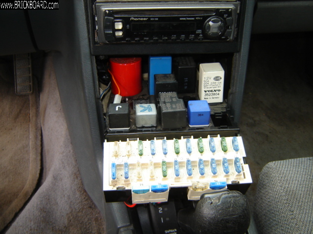
I too need to pull the radio so that I can deal with the fuse box that I was able to get partially out. My car has a Pioneer DH 1100 in it and I am mystified as to how it will come out. I really don't need to pull the radio, it is the radio box surround I need out of the way.
If I can load the picture you can see that I cannot lift and turn the fuse box because the radio mounting box is in the way. Right now I cannot get the fuse box in or out so the car is temporarily off the road.
Any thoughts?
Bob
|
|
|
|
|
Hi Bob. Normally I'd find it simplest to remove the radio in order to give myself extra room to flip the relay tray over.
However, because you're dealing with an unfamiliar aftermarket radio installation, you'll likely find Spook's suggestion of removing the larger relays is well worth trying.
Since you asked, I'll explain the procedure for removing your aftermarket radio.
Aftermarket radios are usually in standard DIN mounting boxes (or sleeves) and these metal DIN boxes are mounted in a plastic mounting adapter that is designed to fit the 740/940 dash locations and existing radio mounting shelf box.
First, you need to get any black plastic trim surrounding the face of the radio out of the way in order to get at the DIN mounting box tab slots on the sides. It's hard to tell in your pic, but I almost see those side slots exposed now just behind the plastic trim. If the radio has a detachable front panel (for security) then start by removing it. If not, then in order to gain access to the side slots you may need to remove the plastic trim bezel from around the face of the radio. There may also be thin plastic trim around the edge of the DIN box (I don't see any in your pic).
Now with the edge of the DIN box now exposed, you need to insert a metal key up the side slots between the radio and the DIN box to release the side clips so you can pull the radio forward and out. These keys often come with the aftermarket radio or installation kit, but any approx 3/8" wide strip of thin metal will suffice (say cut from a tin can) tapering the end back perhaps 1/2" to 5/8" to make a blunt pointed key. You just need to push the key straight in, maybe 1 to 1-1/2" to free the spring clip on the side of the DIN box from the radio case. Google around for some pics or videos of DIN box radio installation if you need a better idea.
Once the radio is out, your next step is to remove the Volvo radio relay box. For 940s, there are two Torx screws in an upper recess, but the metal DIN box will likely be blocking them so you need to remove it. The DIN metal box is normally mounted in an aftermarket back plastic adapter plate designed to fit the 740/940 dash and Volvo radio box. Metrix is a common brand, as I recall. There are little metal tabs around the front edge of the box that are bent out to secure it in the plastic adapter. The plastic adapter plate has stiff plastic tabs on either side that fit into the slots in the Volvo box (same slots the Volvo radios clip into). If the DIN box is a short metal sleeve then you should be able to reach through and get a small screwdriver (even your fingers) behind to release the plastic tabs. If not then you'll neeed to remove the DIN box from the mounting adapter by bending in the little tabs.
Now once you've got the dash adapter plate and DIN box out of the way, you can remove the stock radio box (2 Torx screws in an upper recess for 940s) to give you the added room above the relay tray.
Sound simple enough? Well, after you've done it a few times it actually is.
If nothing else, save this post for the day you will actually need to remove the radio, such as to get at the inside bolts so you can remove the console side panels.
--
Dave -still with 940's, prev 740/240/140/120 You'd think I'd have learned by now
|
|
|
|
|
hi Dave,
I cut and pasted your reply and printed it out so that I can refer to it if I have to pull the radio. Thanks again for a fulsome description of the procedure.
As I told Spook I am trying to repair the high mount brake light which was smashed by what I think might have been a dog. I have checked the rear connections out and they are good so I think my problem might lie with the fuse box and its connections. The standard brake lights work so it is not a fuse problem. I am not getting power to the connector and it runs directly to the fuse box alongside the wires to the left and right brake lights.
I hope you might have noticed the very good transmission light setup. Gives me a thrill every time I change gears!
Bob
|
|
|
|
|
Well, why didn't you say it was that light in the first place? -laugh Forget about gaining access under the relay tray, leastwise for now. If there's no power getting to the 3rd brake light bulb and the other brake lights are working to indicate it's not the fuse or brake light switch, then the next main suspect is the bulb sensor relay (known variously as the bulb out relay or bulb integrity sensor). It's the large red round relay in the back left corner of the relay tray.
Yes, it could be a loose/melted contact in the relay tray socket as you were suspecting, but a far more likely suspect and the first and easiest thing to check is the relay. As a note to others, if this was a 240 wagon then the prime suspect would be a broken wire at the tailgate hinge.
If you've got access to a known working relay then the easiest thing is just to try swapping. Your 960 almost certainly uses the same type, but almost any 1986-on RWD Volvo with a 3rd brake light uses that same red relay.
Otherwise, proceed as follows:
o You've already got the storage shelf removed for easier access, although it is possible to get the relay in and out with the shelf still in place. To make life easier for yourself to insert the relay in the correct orientation of the socket keyway, start by marking the relay with a felt pen, like "F" for front.
o Remove the relay and using a multimeter check it for continuity of the 3rd brake light circuit through the relay between pin 54S (from the brake light fuse #4) and pin S (to the 3rd brake light bulb). If you don't see continuity then the bulb relay is faulty, which I very much suspect will be your case.
o Replace any faulty one with a good used one. If you buy new they're rather expensive. I've had recent intermittent troubles with two brand new cheaper Kaehler aftermarket ones (which use a different solid state internal design) in both my 940s so I no longer recommend those. Repair is usually possible by re-flowing the solder at a few of the contacts on the circuit boards. See the FAQ here and search numerous posts in the RWD forum on how to do that (esp. check Art's posts on the topic which often include pics).
o Now if for some strange reason the continuity checks out, then before going to the trouble of pulling out and flipping the relay tray over for examination, there is one final easy check. I'll mention this trick as it a useful one to know in other situations where you're not sure if power is getting to or out of the relay. Make yourself a test lead wire (preferably solid core, 16g-18g) and wrap a couple of turns of bare wire around the base of pin S on the relay. Make sure bare wire won't be touching nearby pins and that the other end of the test lead won't be shorting out on metal. Now re-insert the relay. When you depress the brake, you should be seeing 12 volts coming out on that test wire (with reference to a good chassis ground point). If so, then the relay is indeed okay and the problem is between the contact in the relay tray socket and the bulb hiolder at the rear of the car. It's at that point you go looking under the relay tray for a loose contact and damaged socket.
Good luck.
--
Dave -still with 940's, prev 740/240/140/120 You'd think I'd have learned by now
|
|
|
|
|
Hi Dave,
I just reached this conclusion as well. My wiring schematic shows the yellow/black connecting wire entering the Bulb Malfunction Sensor at pin S.
The other brake light wires enter at pins 10 and 11.
They are all fed power through three separate resistors that emanate from pin 54s according to my wiring schematic.
But there is no pin 54s showing on the red sensor itself. I have a pin 54, a pin 54L, and a pin 54R. I suspect it would be 54 for the high mount light. The other two would be going to the left and right brake lights. Right?
I will take a read through your latest post and start checking out the sensor tomorrow. It is my number one culprit at the moment. I am expecting it to be an expensive little item.
Thanks once again.
Bob
|
|
|
|
|
No, pin S is to the 3rd brake light as I noted. Although in the Volvo wiring diagrams it's supposed to be 54S as +12V from the brake light switch (through fuse 4), I recall you're right and the relays are just marked 54. 54L and 54R are to the left and right brake light, respectively.
If this is a genuine Volvo bulb relay (not the Kaehler or KAE aftermarket one that is a solid state design) and you're at all handy with a soldering iron then the odds are 95% you can repair the relay and save yourself a lot of trouble and money. You'll want a fairly sharp point tip and preferably a decent 25W-45W soldering iron, not a soldering gun, and some proper electrical solder (which includes a resin flux core), preferably fairly fine gauge electronic solder that often comes in little pill bottles.
Pry off the plastic relay cap using a tiny slot screwdriver around the base. Mark pin S for reference (felt pen is ideal) before removing the plastic base (also mark pin 54L, 54R and 54).
Under good lighting (old farts like me will also need a magnifying glass), follow the pin S circuit onto the two layered circuit boards. Re-flow and add a touch of solder at each major solder point on that circuit that you should be able to follow back to pin 54. Adding a touch of solder is key to a long lasting repair as it makes for a better heat sink, a common problem with many of the relays that Volvo used, such as the fuel pump relays. While you're at it, re-flow the solder points from 54L and 54R that also go back to 54 as they're also prone to failure. Each of those circuits has a separate sensor coil in it, in fact that's all there is in those circuits other than pin connections (and possibly one or two jumper wires, I forget). For now, you can forget about the other lighting circuits and sensor circuits, including the reed relays that go through the inside of the sensor coils. The reed relays are fairly fragile so don't bend the wires trying to straighten them. Some of the inner solder points may be a bit difficult to access, hence the need for a fine solder tip, a hot iron and good lighting. Just make sure you don't leave any solder traces or make bridges to other circuits and neighbouring pins. When you're done, give it a quick flush with isopropanol or contact cleaner and a small toothbrush to remove loose solder and flux residue.
Odds are high you'll have fixed it good as new and be very proud of your accomplishment.
--
Dave -still with 940's, prev 740/240/140/120 You'd think I'd have learned by now
|
|
|
|
|
Hi Dave,
Okay. So I did some soldering and managed to get continuity between pins S and 54, 54L and 54R. I thought I had it built but alas when I put everything together, still not getting a brake light when the pedal is pushed.
I ran power from pin S of the Electrical Distribution Unit to the brake light and it lit up. So I am pretty well certain that it is the sensor. The circuit from the sensor to the light bulb is good.
And the fact that the other brake lights are working indicates that the power to the EDU is there. It is travelling through the EDU and getting to the LH and RH brake lights.
Tomorrow I will take the sensor apart for the third time and I will try a general resoldering. Perhaps the coil between pin 54 and pin S has failed. In which case I will have to declare the unit as hooped. I don't know where I could get such a coil and rewire it in place.
Regardless, it has been an interesting journey.
Bob
|
|
|
|
|
If you have continuity between 54 and S then it should be working. Start by verifying that's still the case and use a middle range Ohmsmeter setting, not simple continuity. You want to see close to zero Ohms equally between 54->S, 54->54R and 54->54L. It's possible one of the solder joints is borderline creating an unbalanced circuit, in fact if you've had intermittent flickering brake lights on the one side that's a distinct possibility so going back and re-doing a bit more of the solder work on those circuits may well be what's needed.
The sensing coil wires are more than heavy duty and won't burn out, but the coating can prevent good solder contact at the board, so do keep that in mind and pull the coils up a hair if they're sticking a bit too far out the solder side.
The next thing I'd do after that is the test lead trick I mentioned to see if power is coming out on pin S at the base of the relay when it's plugged in. If that test shows power out on pin S, but still nothing at the 3rd brakelight then you've got your originally suspected socket contact problem (given that you've apparently proven the wiring from the socket to the bulb holder is okay). Try wiggling the relay while your foot is on the brake to see if the lights blink.
The other thing to keep in mind is that if the circuits look okay on the bench, but misbehave when plugged in then it could be a weak solder joint at a main pin. Those boards are pretty solid so I don't expect a broken trace, but you should inspect for them anyway. You will need some decent iron heat to re-flow the main pins (use a solder gun for this if you have one).
--
Dave -still with 940's, prev 740/240/140/120 You'd think I'd have learned by now
|
|
|
|
|
Hi Dave,
Trying to find where I might have gone wrong on the checking. The wire I used on the test lead was a bit of standard automotive wire that I had around. I cleaned the end of insulation and coiled it around the pin of the sensor. I was going to use some bailing wire which is thinner but decided I would get better conductivity through a copper wire.
Do you think that might be an issue?
Bob
|
|
|
|
|
Stranded primary automotive wire is fine for a test lead. I was suggesting solid core wire so there was less likelihood of an errant strand sticking out to short on a nearby pin. Just be sure you wrapped it on the right pin and that your meter is connected to a good chassis ground point. Try measuring on one of the other 54, 54R or 54L pins just to make sure you can see voltage.
--
Dave -still with 940's, prev 740/240/140/120 You'd think I'd have learned by now
|
|
|
|
|
Today I hooked up a new test wire [solid core] to pin S and connected it to B+ and the brake light went on. I did not need to push the brake pedal. It went on as soon as I connected it. So . . I am trying to interpret exactly what is going on. I am using the original bulb sensor.
Looking at the schematic that makes sense because the lead from the brake light bulb back to the bulb malfunction sensor is continuous. Power applied to S will flow down the wire through the bulb to ground
By the way, I checked the replacement sensor for continuity and it shows fine between S, 54, 54L and 54R.
We did discuss this earlier but am I correct in seeing pin S as the exit power pin leading directly to the brake light bulb, and in seeing pin 54 as the power entry point to the three brake light circuits, i.e., power goes in at pin 54 and feeds pins S, 54L and 54R.
If you are getting fed up with my musings and questions, just tell me to shut up and move on--I wouldn't blame you!
|
|
|
|
|
I am flummoxed now. I bought another unit, admittedly a used one, and I still have the same problem. No centre brake light.
|
|
|
|
|
It's always possible that the used sensor you got is a dud with the same problem, but I rather suspect not as your test results remain a bit confusing. At least it was a nice day for a drive to Nanaimo.
Back to basics. Let's review:
1) Left and right brake lights work normally, just not the third brake light, right? And you're seeing the same behaviour with the new (used) sensor?
2) With an ohmmeter, on the bench the sensor has near zero resistance between pin 54 and each of pins 54R, 54L and S, right? And you're seeing the same with the new sensor?
3) With the bulb sensor removed, you can apply 12 volts directly to the Yellow-Black wire at relay tray socket contact #5 corresponding to pin S and the 3rd brake light (only) now works, right? I presume the relay tray socket doesn't look visibly melted or blackened and from the backside the contacts are more or less equally seated and equally snug. For testing purposes, it doesn't really matter where you pick up the 12 volt source, but it will be best to have the park/headlights off (meaning ignition not in KPII) to avoid complicating the mystery with any possible grounding issues that might be at the rear (or front) lighting.
4) With the sensor installed and a test lead wrapped on the base of pin S, you cannot see 12 volts with reference to a good chassis ground point when you depress the brake, BUT you can see close to battery voltage if you do the same thing with the test lead wrapped on one or all of pins 54, 54R or 54L, right? Again, check both the old and new sensor.
It only makes sense to me that one of those statements above needs to be incorrect. Don't get too frustrated over this, come back to it tomorrow with more patience if you need to. I'm sure I've had occasions where I had trouble making sense of the sensor, lol.
--
Dave -still with 940's, prev 740/240/140/120 You'd think I'd have learned by now
|
|
|
|
|
Hi Dave,
With the original sensor installed and a test lead wrapped around the pin here is what I found:
Pin voltage measurement brake light
S 6 1/2 volts ON without pedal being pressed.
54 12 volts OFF Pedal pressed or not
54L 6 1/2 volts ON without pedal being pressed
54R 6 1/2 volts ON without pedal being pressed
I might have been using the battery ground lead instead of its B+ lead when I originally tested pin S. I seemed to have some kind of blind spot for a while. I don't know what to make of these readings. I will test the new sensor tomorrow.
Bob
|
|
|
|
|
Hey Bob. Aha, we're making progress! 6-1/2 volts, hmmm? Keep at it, going over my checklist as thoroughly as you can, being careful to use your meter, chassis ground and B+ sources correctly. This is the 940 with the bad 3rd light assembly, right, so make sure everything electrical is clean back there. I'll do my best to keep following and helping when I get the chance between doing tax returns and other assorted non-Volvo things in my life. As I've thought many times before, if it wasn't for this Covid stuff it might be faster to just take the 2 hr drive up there, kick you in the ass just for the heck of it, and get this done together, huge laugh! Cheers
--
Dave -still with 940's, prev 740/240/140/120 You'd think I'd have learned by now
|
|
|
|
|
Hi Dave,
Using a separate battery power source and the car battery disconnected and the wire power loop installed, here are the results
New unit
I measured 12 volts for all four pins, i.e., S, 54, 54L, and 54R. The high mount brake light came on for all four measurements without having to press the pedal.
Old unit
Same as the new unit EXCEPT for pin 54. It measured 12 volts but there was no light on and pressing the pedal did not bring it on. I checked the pin twice and got the same result.
I did have a mishap. The bare power wire I was using got underneath the white relay while I was busy trying to insert the red sensor and the wire began to smoke and got quite hot. I continued to check the red sensor after that incident and nothing seemed to have been affected.
Bob
|
|
|
|
|
It doesn't help we're both composing posts at the same time here, plus I often end up editing mine even after you might get your emailed notfication, so always use the link in your brickboard email notifications to make sure you're reading the latest revision of my thinking.
So if I'm reading you right, with the bulb sensor installed and 12 volts applied from an external source directly to the base of pin 54, you're now seeing 12 volts out on all of pins 54L, 54R and S on the old sensor AND the new sensor? The only difference is the 3rd brake light working when you tested the new sensor? Yet only two of the three brake lights were previously working with the old sensor? Hmmm? Such inconsistent behaviour smells like a marginal contact in the sensor socket, something you were originally thinking. Do keep that in mind as you complete your testing.
--
Dave -still with 940's, prev 740/240/140/120 You'd think I'd have learned by now
|
|
|
|
|
Hi Dave,
When I look at the schematic, power is entering the sensor at pin 54, and it exits through pins 54L, 54R, and S.
So, when I disconnected the car battery all power to the circuit was lost. In retrospect I should have realized that with the brake pedal not pushed, power is not available to the circuit anyways. As long as I don't push the pedal I will not get a conflict of power sources.
When I connected the external battery to pin 54 and the light came on in the NEW sensor, what does that tell me? That power is now able to traverse the sensor, run through the wiring at pin S and light the high mount bulb. BUT when I just put everything back together and hit the pedal, the high mount bulb does not light.
AND the light did NOT come on in the OLD sensor. [not shouting here, just emphasizing!] So power is NOT traversing the sensor and exiting through pin S on the old sensor.
Conclusions:
1. stick with the new sensor
2. check the power from the pedal with the sensor pulled out.
3. check the brown/yellow wire connector for continuity. I think it is position 5 on the connector.
|
|
|
|
|
Valid conclusions, plus a few more thoughts for you here
Seemingly the new sensor behaves better during testing than the old one, so definitely go with that one until everything is working, then you can go back and re-test the old one to see if it still works.
|When I connected the external battery to pin 54 and the light came on in the NEW sensor, what does that tell me? That power is now able to traverse the sensor, run through the wiring at pin S and light the high mount bulb. BUT when I just put everything back together and hit the pedal, the high mount bulb does not light.|
That tells me your new sensor works just fine and that when you put everything back together you are no longer getting power to pin 54 when the brake pedal is depressed. Either the brake switch is faulty or you didn't have the car battery re-connected or you have a contact issue in the socket.
Are you sure the other brake lights are still working normally as you earlier stated? Apart from a few possible mis-steps during testing, it's only the 3rd brake light misbehaving? When you're sitting in the car doing testing it's not always easy to know if the main brake lights are illuminating unless the rear of the car is close to a wall. I'll sometimes keep a board propped up against each tail light so I can see a reflection.
I have completely discounted the brake switch from your issues as you said the other brake lights have been working normally and I believe some of your testing found voltage at 54, 54R or 54L, just nothing on S and the 3rd light only illuminates when you apply external voltage either directly to the base of pin S or to pin 54 of the new sensor. I will mention that the brake switches in the '94-'95 940s can be problematic at this age. As they wear, operation can become intermittent. They're a different design than the earlier barrel shaped ones and frankly a major, major pain to remove and install. Although a cleaning of the internal contacts can get you a bit more life, both mine finally needed replacement in the past couple of years. You can meter test the brake switch in place using aligator clipped test wires, but be cautioned that an intermittently failing switch can look good during manhandling and testing.
You're testing also suggests the Yellow-Black wire for pin S is good to the rear. However, the inconsistent test results are suggesting you may have a contact issue in the relay tray socket. Inspect the integrity of the socket more closely from above and below, with particular attention to the pin 54 and S locations. Use spray contact cleaner (not WD-40). If it turns out one of the contact sleeves has expanded due to heat or physical effects then you can try to carefully close it up a bit, but save that thought until you better identify the issue.
--
Dave -still with 940's, prev 740/240/140/120 You'd think I'd have learned by now
|
|
|
|
|
Okay, I am using your power source at fuse 3 now and I am using the ground wire from the cigarette lighter. I checked and got twelve volts from fuse 3 to the ground wire.
So I grounded the meter with the cigarette lighter ground.
I removed the sensor.
I put the other meter lead into the now open socket where pin 54 should be.
Push the brake pedal.
And I get no voltage showing.
When I look at the schematic I see power flowing past the brake pedal to the three brake lights after entering at pin 54.
Where am I going wrong? I haven't checked the other brake lights lately. Will check today and get back.
|
|
|
|
|
You're not going wrong at all, in fact this is slowly starting to come together. Your earlier testing showed the brake light circuit of the new bulb sensor seems to work and the old sensor may well be faulty.
Your testing is now showing you're not getting power from the brake light switch to the realy tray. That suggests a faulty brake switch exactly as I alluded to in my last reply. Dealing with two problems at the same time may well have been confounding the issue for you in amongst trying to master new electrical testing techniques.
If you can confirm that you're not seeing a reliable 12 volts in the socket for pin 54 then that now moves your attention to the connector at the brake switch. I'd suggest using a wire wrapped around pin 54 for testing so you don't have to worry about making sure the tip of your meter probe is contacting properly in the socket as it can be a bit awkward to see what you're doing in there. Try the pedal a number of times slow and fast as worn/dirty internal contacts may make for an intermittent signal or less than full battery voltage (compared to the direct from battery voltage you can see at fuse 3). Now if you somehow do happen to see 12 volts then I'll be shocked if you're not also seeing some brake lights at the same time, hopefully even the 3rd brake light.
Post back once you confirm it's now at the brake light switch. I would suggest starting a new thread at this stage as this one is getting horridly long and off the original 940 radio removal issue. I'll pick up your problem there and try to help you through brake switch replacement if needed as the new style switches are indeed a bit tricky to deal with.
--
Dave -still with 940's, prev 740/240/140/120 You'd think I'd have learned by now
|
|
|
|
|
Hi Dave,
I have started a new thread and have put your last commentary in it as a start point. More mysteries have revealed themselves.
Volvo centre brake light not going on.
Bob
|
|
|
|
|
Hi Dave,
I am thinking of pulling the battery on my 240 and using it as a power source. Right now I am using the car battery with long leads and yesterday I was feeding power to the circuit and to the test lead from the same source. I am not sure if this is corrupting the readings or not. I want to check the other sensor today and will try to set up.
obsessively, Bob
p.s. I have not done my taxes yet and the lawn is looking fiercely long. If I disappear you know what has happened.
|
|
|
|
|
Probably not the best idea to introduce two batteries into the equation. For picking up a 12-volt battery (B+) source for testing, the best option where you're working is at the relay tray. There are a few options, but the one that appeals to me most for your purposes here is Fuse #3 (next to fuse #4 which is for the brake lights). Fuse #3 is a 30 amp source direct from the battery and is used for power seats, so not critical to vehicle operation or involved with your testing. Using an alligator clip under the fuse panel can be problematic, so better to pull the fuse and insert the end of a test lead or test wire into the hot side of the fuse socket when you need 12 volts. Keep in mind which side is hot as it will foil your testing if you're inadvertently touching the wrong side (you can always use a mark or piece of tape as a reminder). Folding the bare end of a solid core copper wire into a U works well if you need a test wire to stay more securely in the socket. Naturally you want to be extra careful with the other end of any hot test wire so as not to accidentally short it on metal. I believe you'll find the lower side of the fuse socket is the hot side (has a brown wire leading to it), but do check that with your meter. Also a reminder that the metal cross bar in front of the relay tray isn't a chassis ground. A good ground source for testing purposes is the tab with the black wire on the cigarette lighter. Also make sure the battery in your multimeter is okay as a weak battery can give you incorrect readings.
I'm getting increasingly curious as to the source of your problem as it's not overly apparent to me at this point. Although it very much seems it should be a basic conductivity issue of volts getting from A to B, I'm starting to wonder about a sensing circuit issue that might be similar to something I've encountered.
I forgot to ask an important question, is the bulb out indicator light working (on with all the other dash inicator lights before startup) and when the engine is running does it illuminate to tell you that the 3rd brake light isn't working when you touch the brake?
--
Dave -still with 940's, prev 740/240/140/120 You'd think I'd have learned by now
|
|
|
|
|
1. New sensor in place and LH and RH brake lights work. Centre light does not work. Same as the old sensor.
2. Both sensor show zero resistance between pin 54 and pins 54R, 54L, and S.
3. I will have to do this check tomorrow. But I did run power to pin S using a new solid core wire wrapped around the pin and the centre brake light bulb lit up. Without having to push the brake pedal. This makes sense if "s" on the wiring schematic corresponds to "S" on the sensor.
|
|
|
|
|
I disconnected both brake lights and pushed the brake pedal with no result once again. I am going into Nanaimo today to pick up a used replacement from Chapman's. At least I will know for sure if the replacement unit gets the brake light working. Otherwise, who knows.
|
|
|
|
|
Thanks for the reply, Dave. I will follow through with your suggestion to take the LH and RH brake light bulbs out and to see what happens then. I have not bought the replacement sensor yet. Still keeping my fingers crossed.
|
|
|
|
|
Hi Dave,
I tried the test lead trick and there was no power showing on the meter. And of course, nothing at the third brakelight.
Wiggling brought no response from the centre brake light either.
I will see if I can get a used one. New one is about two hundred Canadian.
frustratedly, Bob
|
|
|
|
|
That's a bit weird that bench testing shows full continuity from 54->S yet when installed no voltage is detectable using a test lead connected to the base of pin S even though the other brake lights on 54->54R and 54->54L are working okay. If it's not a bad contact in the tray socket or bad solder joint on one of the boards (including all the jumpers and connecting pins in that thought) then that only leaves me thinking about a cracked trace on a board, something I haven't encountered.
I will mention that the 3rd brake light sensing circuit is different from all the other lighting circuits. There's no left-right voltage for comparison to detect an unbalanced circuit indicating a burned out bulb, so it has to compare the 3rd brake light to a fixed resistive load that approximates a bulb. That in itself shouldn't affect your problem, but I now recall some of the 3rd light circuitry is on the upper board (that dates back to 1986 when they had to add ability to sense the newly mandated 3rd brake lights, which they initially tried to do with a three wire sensing coil). Did you try reflowing the solder at both ends of the stacking jumper legs? They're a bit tricky to get at, so perhaps you missed a solder connection that is still bad and can't handle a load even though it can handle a test current (I wouldn't expect zero ohms and zero volts though).
Along that same line of thinking, here's a couple of more things to try before we move on here. Remove/disconnect the left and right brake bulbs to take those circuits out of the equation. Now see if the 3rd brake light wants to work and/or if there's now measurable voltage at pin S using your wrapped test lead. You can also double check that applying 12 volts directly to your test lead wrapped on pin S will turn on the 3rd brake light to re-confirm that circuit to the bulb is okay. If that testing still fails then I'll agree to declare the sensor is beyond hope and your autopsy has failed to establish the cause of death.
This is about where I expect our Art Benstein to be jumping in with ideas if he's following this thread as he understands the subtleties of that bulb sensor even better than I do.
Now as for replacement, yes, the Volvo ones (usually made by Hella) are grossly expensive. I'm sure Chapman will have used ones for you, but don't expect them to be cheap. Many of the online suppliers like FCPEuro have stopped selling the genuine Volvo ones and now only sell the KAE ones, which are about half the price. As I mentioned, I've had intermittent sensing problems with two brand new KAE ones tried in both of my 940s, so I'm personally leary of them, but I have not seen such comments from others. Perhaps there's some miniscule thing a bit different about the bulbs I use that puts them at the edge of what KAE designed the units to detect as normal current. That gives me an idea, I should try one again as I've just put new batteries in both cars and that made a difference in baseline voltage and headlight brightness, which was the circuit that seemed to be overreacting the most in both cars.
Having said that, once you've confirmed your sensor is gone (are you able to try another car?) it's well worth converting it to a bypassed unit. If nothing else, it will make a great spare until you can source a cheaper replacement. Many of us, now including me with one our 940s, use a bypass unit permanently and forget about having an idiot light to tell us a bulb is acting up. What you have to do is de-solder everything off the board and use jumper wires to directly connect all lighting inputs to their left, right (and centre) outputs. It's not hard to do as long as you know which pins are which. I haven't gone looking, but there may be something on that here in the FAQ. I do know there have been a number of posts here in the RWD forum over the years, including some good pics on what a tidy soldering job Art can do. You can probably find stuff on other sites as well. I can also go looking for you if needed. If you have more questions on doing this then post back.
This thread is now way off topic from radio removal and should have been restarted as a new one, so I hope others are following in case they have additional ideas for you.
--
Dave -still with 940's, prev 740/240/140/120 You'd think I'd have learned by now
|
|
|
|
|
I can get a used one for sixty-five Canadian at Chapman's. I think I will go for that. Then I will get some idea of just whether it is the unit itself or not.
|
|
|
|
|
Hi Dave,
I looked back over my notes and found your test lead check, which I will do later today.
I just checked the unit for ohm readings and got full continuity on all three check points, 54 to S, 54 to 54R and 54 to 54L.
My Radio Shack meter has three ranges [Rx1, Rx10, and Rx1K] and I checked the resistance on all three settings. All registered zero ohms.
Will get back to you when I have completed the test lead check.
muskox37
|
|
|
|
|
Hi Dave,
I have probably forgotten this trick or mislaid it. Could you give me a heads up once again, please.
Bob
|
|
|
|
|
Hi Dave,
Okay. No continuity between S, 54, & 54L.
There is continuity between S & 54R however. This would explain the right brake light operating when the centre light is not. Perhaps there is some back route between the left and right lights that allows the left light to flash.
Looks like I will be doing some soldering today. First I will have to use your directions to open up the bulb malfunction unit. I do have the 'official' unit, i.e., Gluhlampenkontrolle 12v 5KG 004 919-05 so it is worth a try. I have asked for a quote from Volvo Cars Victoria for a new one and I am expecting something in the hundred dollar range.
I am intrigued by the idea of fixing this one however.
Bob
|
|
|
|
|
In the last main paragraph, make that "radio mounting box" (aka. shelf) not "radio relay box", I timed out on being able to edit the post
--
Dave -still with 940's, prev 740/240/140/120 You'd think I'd have learned by now
|
|
|
|
|
Dear muskox37,
Hope you're well. Remove the relays and you should have head-room to pull out the fuse block, so that you can access the under-side of the fuse block
If this is the first time you've pulled the fuse box, the thick wire bundle under the fuse block will be "stiff", as the wires haven't been moved for 25 years or so. Warm the wire bundle with a hair dryer, as that will make the wires more flexible.
There should be enough "slack" in the wire bundle to allow the fuse block to be pulled forward (towards the seats) so that the fuse block can be inverted.
Hope this helps.
Stay well.
Yours faithfully,
Spook
|
|
|
|
|
Hi Spook,
Once again, thank you for a common sense solution. Dave supplied me with the ins and outs of radio removal but I will certainly try your way first. Taking one of these radios out seems to be a real challenge.
When I tried to push the whole business back into place I was unable to relocate it properly in its white bracket. I will take the hair dryer to it when I get to the job again.
What I am trying to do is to get the high mount brake light to function. I could get no power to the connector and from what I have seen in the wiring schematic the yellow/black wire runs directly to the fuse box. I loaned the car out and it came back with a smashed brake light. I suspect a dog might have got back in there. I have checked out the bulb and its holder and all of that works so I am left with the notion that the connection to the fuse box is my major culprit. Both of the regular brake lights still work so it is not the fuse.
Your input is much appreciated.
muskox37
|
|
|
|
|
Dear muskox37,
Hope you're well and stay so. Check the third brake light's ground wire. The problem may be coincident with, but not caused by, the dog's damage.
Hope this helps.
Yours faithfully,
Spook
|
|
|
|
|
Hi Spook,
A brief note. Looking like the bulb malfunction sensor at the moment. I will run a few tests on it and see if it is functioning properly.
muskox37
|
|
|
|
|
Dear muskox37,
Hope you're well. Does your cruise control work properly?
If not, that implicates the bulb burn-out sensor.
Hope this helps.
Yours faithfully,
Spook
|
|
|
|
|
Good morning Spook,
I did think the ground wire might be an issue so I devised various ways of hooking up the light and its holder between the power wire and a ground [I used the bolt holding the seat belt in one instance]. I also checked the ground wire for continuity using an ohmmeter. I am fairly certain it is not the issue but I will keep that solution in the back of my mind if I am unsuccessful at finding any issue with the power wire and the fuse box.
I forgot to push the brake pedal on a couple of occasions so I could still have managed to not get a light through what we called 'finger trouble' in the air force.
muskox37
|
|
|
|
|
To add to the link that Spook gave you to the FAQ article.
The key to removal is visualizing what the clip tabs look like on the side of the radio and how they are normally sprung outward to engage in the square slots in the side of the radio shelf box. You have to squeeze those tabs in against the radio to allow it to be pulled forward. Ideally there’d have been pics in the FAQ to go along with the text.
This Youtube video I just found shows the side tabs and removal process reasonably well.
Volvo 940 CR-915 Radio Removal
Note that the screwdriver or whatever that you poke into the slots has to be narrow enough to fit far enough in to reach the lip of the tab. It may take a couple of attempts to figure out how to wiggle out one side a bit and keep it pulled out with your fingers in the cassette slot while you free the other side.
--
Dave -still with 940's, prev 740/240/140/120 You'd think I'd have learned by now
|
|
|
|
|
Dear Robbthecarguy0,
Hope you're well and stay so. Carefully!!!
More seriously, see: https://www.brickboard.com/FAQ/700-900/RadioAntenna.htm#RadioRemoval .
Hope this helps.
Yours faithfully,
Spook
|
|
|
|
|

