|
|
|
I have never had to replace a FP relay on my many 240s.
I understand it is a good idea to carry a spare on the long trips I often make.
I have three used spares, two that look like new on the inside.
I was attempting to test them with an ohm meter. There are zero ohms across every possible combination of terminals. I expected to have resistance across the windings of the two solonoids. Dont know the actual terminals of the winding. Is my assumption incorrect, and can you test this relay with an ohm meter?? Or can you only test it by installation?
|
|
-

|
|
Since this comes up now and then, I'll add my two cents by noting how I have tested the relays.
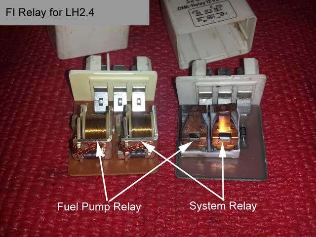
My electrical experience suggests the several ways the electronic assembly we call a relay (not Bosch) can fail. The most commonly written about failure is where the frame of the actual relays inside the box is soldered to the circuit board. Also heavy connections to the socket terminals suffer cracked solder. The fix is to reflow the solder.
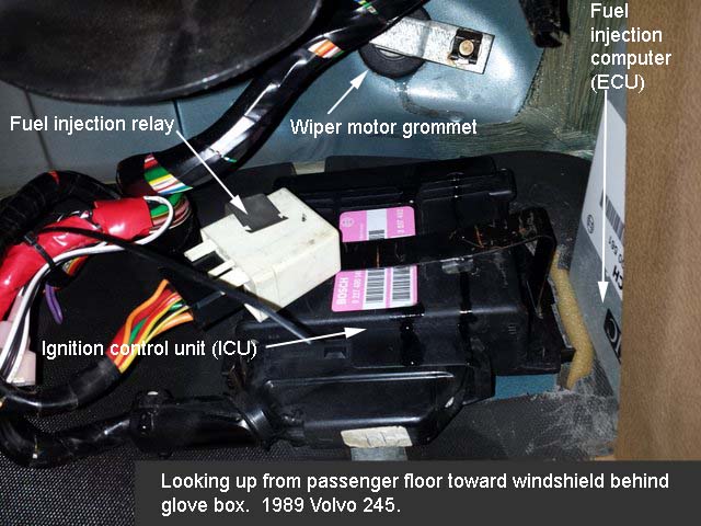
Newer versions of the same assembly have improved this weak point, so the skew of failure causes has, in my experience, moved to the human factor. The more modern version will probably fail due to its being left hanging by its harness connection by the replacement installer. This mistake removes the drip loop established by the factory and allows the leaky windshield/leaky wiper grommet/leaky cowl to cause corrosion damage.
The internal circuit is simple to trace if you take the cover off and look. You'll find a diode in series with the system relay coil, causing your resistance readings to confuse you.
Circuit inside assembly:

According to my observations, contact closure resistance has never been a factor in these assemblies. If it were, I'd find heavy black soot around the silver movable contact.
A surprising number of failures have been with the coil itself, where its fine winding is broken near the terminals or even within the bulk of the winding. These can be solid failures, but more insidious, intermittent with temperature. The coils get quite warm, each dissipating over 2W and contained in a small plastic box, so there will be metal fatigue in the fine wire as a result of the heating/cooling cycle.
The myth exists that the relay is under-spec'd. These relays are 30A relays and the max load experienced by either one of them is about 6.5A. That's why I don't see black soot at the contacts. However, some enthusiasts felt the heat that accumulates in this dual relay box normally, and surprised by it, have drilled ventilation holes in the case. Don't do it. They run warm due to continuous coil dissipation, over two watts per relay, not having anything to do with the load current they switch. Here's a demonstration which I hope would bring my point home:

============================================================================
So, bottom line: First, I open the relay and look for visible evidence of corrosion (they should be pristine) and in those relays needing it, especially the originals made in the 80's, reflow the solder.
Then the test is to install them and put some "miles" on them to ensure the intermittent failures are excluded as best as possible.
And I make sure to leave a drip loop and put them back so water doesn't follow the wires down into the bottom of the relay box.
============================================================================
Drip loop illustrated:
Two versions of the same part:
Most of us carry a spare. I carry a jumper wire and a test light, only because my desire is to learn something from each failure when it occurs.
--
Art Benstein near Baltimore
"Being nice to people is so much easier with your mouth closed." -- Benjamin Davis
|
|
-
|
|
|
Using your pictures, one line, and instructions, and my old Simpson 260, I was able to confirm resistance between 30 and 86/1, then 86/2 and 85, on all 3 relays. Sure enough, between 86/2 and 85, I had to reverse the leads because the diode prevented an ohm reading in my initial reading.
Thanks to you and machine man, I was able to confirm that the relays have good coils, and realize that to actually confirm function, I need to install them and drive the car for a while. As the cowboys say, " much obliged".
|
|
-
|
|
|
Hi,
I thought I would write a little about what I know of this subject, or maybe how little, I know about this subject, considering others, that might be the gurus in electrical stuff! (:-)
I looked at the link in the other post on how to check a Bosch relay. It pretty accurate and all, to test a single pole single throw relay. (SPST)
The numbers given out for “resistance references” will vary due lengths of meter leads and the meters own internal circuitry.
A display of a “Zero” or .0000 to the right of a decimal point on digital meters means a part of a “one something” no matter what it is.
In ohms, this represents the shortest path of a “perfect” circuit path. This varies with connections and contact surface conditions of a relay too.
The resistance value is a comparable number against current flow. Only problem is the ohmmeter uses a small battery voltage source that in most all cases will not damage components.
The Perfect part is not going to really happen, unless you are willing to ignore lots decimal places to the far right!
With that said, you don’t know which way the ohmmeters battery voltage travels or what it is reading in series or in parallel either.
Ohmmeters are not as sensitive as one might think, so you are “correct,” that the relay needs to be tested under its “rated current load” with the operating voltages monitored.
In a factory, they use a testing fixture setup that operates them as fast as they can click on and off!
The gauges that are in those fixtures have limits set to be within certain ranges or its tossed!
For us to invest, in things to that end, is not practical.
Taking a reading of voltage drop out for or in the circuit is “exponentially” more sensitive to help in locating a faults.
It works that the first few digits can mean a whole lot of resistance is present.
On DC circuits reading only one side of the power polarity or the meter leads in parallel, shows a differential proportional shows up well. Like in trigonometry, there are ratios from which end you are working on.
This works in circuit boards and any wiring in general.
This is why oscilloscopes are so crucial in the measuring working voltage potentials small signals presented in today’s electronic circuit systems. .2 to .7 of a volt can mean good or bad I’m finding out!
The point I’m getting is about the board pins may be common one side of the magnetic coils and diodes. You got to know what is controlling those coil and power output terminals electrically.
Ohmmeters are not always the best suited tool. It’s just too quick and dirty with its flaws.
The all LH system(s) a relay has always been used for control circuits doing the same thing.
But, it just happens many times a relay can have more functions built in. Black boxes are even worse!
This change in LH systems took place around about 1984.
Before the combined relay you could switch identical relays around and change the symptoms to trouble shoot the functions.
Not testing fixture needed because it is already there!
This helps in fault finding the fuel pumps were not running.
Do a switch around and then they do, but the car won’t start, you knew the injectors were not firing.
Today carrying a working spare, since they are so small, works the same.
Having a tool to open up any relay cover suspected of a failure is handy too!
You can get in there and wrap the contacts down with something non-conductive, like a rubber band.
You close them in their intended direction.
In most cases I have seen, that’s toward the magnetic coils. (:-)
You just have to remove it or those pumps will run all the time when the fuse panel gets power.
I have used a shoe string once and it got me home.
Rubber bands rot away like nobody’s business! Don’t bother keeping them in a glove box or wrapped around something. I have had them crack and stick to the item. Air melting?
So that’s my “spiel.”
As usual, its soaked up like gravy onto a biscuit or not! (:-)
I see, just before I posted all of this, that you may be reaching this conclusion already!
Just didn’t want to throw it away, like a bad relay! (:-)
Phil
|
|
-
|
|
|
Once again, I am reminded how each and every day, at some point I feel smart, and at another I feel stupid. This saga was begun by me finding 3 used FP relays in my parts stash, and wanting to confirm their function with an ohm meter. Your lengthy explanation is appreciated and enlightening.
I really like your story about the shoe string and rubber band emergency procedure.
|
|
-
|
|
|
Hi there and thanks for the reply!
Happy to have helped someone store some worthwhile data in the back of their brain vault.
We are the sum of our experiences and what churns around up there between the ears and eyes!
It was my desperation, that inspired that use what was available for a solution!
It’s nice when the light bulb comes on and it doesn’t burn right out on ya!
I don’t know much about being a cowboy or even a farmers boots.
I was glad I wasn’t wearing “my normal” slip-on shoes of today though!
I keep spares of shoes and relays available.
Phil
|
|
-
|
|
|
when relays fail, it's because they can't pass enough voltage to run the part. if you have a running car and a selection of used relays, swap them instead. ohms testing isn't going to give enough info.
|
|
-
|
|
|
You are correct. Installation would be the best confirmation, even for a new relay. Having a spare, especially a new part, that does not work but that you think works can ruin your day. ( A hard lesson learned by many )
Thanks
|
|
-
|
|
|
Here's one method. Google brings up numerous videos.
https://forums.tdiclub.com/index.php?threads/how-to-check-a-bosch-relay.372092/
--
Post Back. That's whats makes this forum work.
|
|
-
|
|
|
That was a nice web site.
But explains a simple relay, which I already understood.
The Volvo FP relay has two coils. I expected to find resistance between 3 or 4 terminals, but that is not the case. With my old Simpson 260, I find 1.8 ohms between #30, and #86/1 on all 3 relays. No other resistance found.
This doesn't make sense to me. Is this an oddball relay, like the headlight dimmer relay on late model 240s? ( That one really had me scratching my head until I took one apart.
I may just have to check them by installallation.
Thanks
|
|
|
|
|