|
|
|
Hi,
After my first and only speedometer issue in a 240 about 5 years ago, I became aware of the value of the cluster boxes. I was able to resolve my problem without expense thanks to the board, but I've been keeping my eyes open and put words out to where I now have 8 boxes on a shelf in my shop. There's been a lot of 240's around here that have gone to scrap in the last couple of years.
Two speedos are mechanical and one's a 4 pinner, but I decided this past summer to cycle the rest of the boxes through my 91 non ABS to get an idea of what condition they're in. I know the speed sensor output to the ECU may not work, but I think the speedo, odo, lights and gauges should.
The first two needed gears and a few lights which I replaced, but the third one has me stumped. It's wearing 87-240 in marker on the back and it's speedo drops to zero repeatedly and often. The slightest tap on the dash brings it back to speed almost every time.
I expected to find a fault in the L connection or the speedo pins so I hooked it up using the Benstein Nobel Worthy Troubleshooter.
I found it very amusing to sit in my car with a cup of coffee, motor off, and the speedo and odo counting away. My first thought was " I've got to find a job where I get paid by the mile." That's brilliant, Art.
I composed myself and let it run 10 miles and no amount of banging, twisting, or shaking could make it fail. I'd retensioned the L before the experiment so I presumed that was the problem, but after 2 days of flawless operation it resumed it's bad habit. Since then I've had it in and out twice and gone over the power lines from the L to the PCB and all seems well. I've also reflowed the motor connections on the board and verified the car's circuits by replacing it's original box. It works fine.
I'll keep at it. I've never had the face or needle off of one of these and wonder if there's something there I should look at. I see how the motor on the PCB drives the gears for the odo but it's unclear to me what makes the speedo needle move. Any ideas would be appreciated.
I don't know if it's relevant or not, but of the hundred or so times the speedo needle has dropped to zero, on two occasions at 50 MPH it as dropped to around half speed. Again a light tap brings it back.
Regards. Peter
|
|
-
|
|
|
Hi,
Just thought I would put in a word to match up with Arts information on how the needle moves.
The newer electronic speedometers are a mixed bag of old and new technology.
Here is what I found on my quick and little of effort research.
I put in a search for how the Eddy Current speedometers worked.
https://auto.howstuffworks.com/car-driving-safety/safety-regulatory-devices/speedometer3.htm
I learned about this a long time ago, because on my bicycles I had two speedometers wear out and gleamed one more learning lesson of value from them before throwing it away.
I hit a puzzle for sure as I was curious of how does a spinning magnet turning under an aluminum cup every work and back then if you were curious in those days,, you had to go to a library!
After you read this link, the rest is up to imagination.
I know if you have seen swirls of water in a river. Just put that inside the aluminum cups walls and it will help identify magnetic fields being, temporarily held, in that type of mechanization.
The article above fits into what Art is saying about current coming as it’s signal driven and hanging on to the same analog sensory output for us.
I hope this fills in that I would change any capacitor in a circuit that is having issues.
Especially, when things are intermittent!
They are the oldest technology left in there and they fail in some of the weirdest ways!
To backup that thought, the ones in that speedometer are made with rolled up aluminum foil!
Phil
|
|
-
|
|
|
Thanks, Phil
Your advice on the capacitors is well taken, but I'm usually slow to replace parts unless they can't be tested.
The fault has recently become steady so that may help to resolve it. Someone long ago showed me how to test capactors using a meter. It involved switching leads and seeing the needle fall but I don't remember details like was the meter measuring volts or ohms, and if the cap is powered or not.
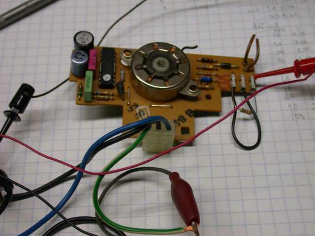
I may end up there, but as the fault is holding, I'm being optimistic and hoping I'll be able to trace the power to a definitive point. I'm sadly lacking in electronics, but in Art Benstein's drawing of the CB the caps seem to be only on the meter circuit. This very well be an incorrect assumption because that power then goes into the black ITT box, and I have no idea what that unit is even called, let alone what kind of mischief goes on in there.
Stay tuned,
Peter
|
|
-
|
|
|
Hi Peter,
In this circuit, the two electrolytic capacitors can be removed and the basic function will remain. The one larger cap I mentioned is there to smooth the speed meter deflection. A very unlikely fault could result in it shorting out intermittently inside, which could cause the needle to drop to zero, but this would be independent of the odometer. Very unlikely.
The most likely fault with the electrolytic capacitors in this gauge would be diminished capacity as they dry out, and it is unlikely a driver would ever notice the effect. How different this is from the Yazaki gauge the 7/9 folk are saddled with, where the caps leak and destroy the circuit board.
--
Art Benstein near Baltimore
Being right is highly overrated. Even a stopped clock is right twice a day.
|
|
-
|
|
|
"I see how the motor on the PCB drives the gears for the odo but it's unclear to me what makes the speedo needle move."
Hi Peter,
If the speedometer drops while the miles keep ticking away on the odo, there's very little left to go wrong. I haven't had this occurrence, so I can say I'm stumped for an internet suggestion based on experience.
When you look at the blue and black wires leading from the board to the speed meter, you are seeing most of the vulnerable aspect of this part of the circuit. Then, if you follow the traces on the circuit board, from the blue wire especially, you may see some solder connections you didn't reflow, perhaps, and the 220 microfarad capacitor in the corner.
If all that looks good, then I'd be getting out a powerful light and a good pair of specs to examine the meter itself, which is least repairable of all, and as delicate as an instrument can be hauled around in a car for hundreds of thousands of miles. It works like this: D'Arsonval Movement
--
Art Benstein near Baltimore
You can say any foolish thing to a dog, and the dog will give you a look that says, 'Wow, you're right! I never would've thought of that!'
- Dave Barry
|
|
-
|
|
|
Hi Art, Thanks for the reply.
The term D'arsoval Movement is etched in my memory but I don't recall ever understanding what it meant. It's simple enough and explains the M in your hand made drawing of the circuit board. It's beyond my capability to fully understand that drawing but my guess is that the signal from the speed sensor is shared by both the motor and the meter to regulate them.
I'm slow to respond because I wasn't sure if the odo was failing with the speedo. I seem to remember that it was, but the unit has been in the car for over 4K and I've gotten into the habit of smacking the dash when the needle gets my attention. Looking at the odo takes a conscious effort. We had a 200 mile return trip to Montreal planned for last weekend so I thought I'd verify it then.
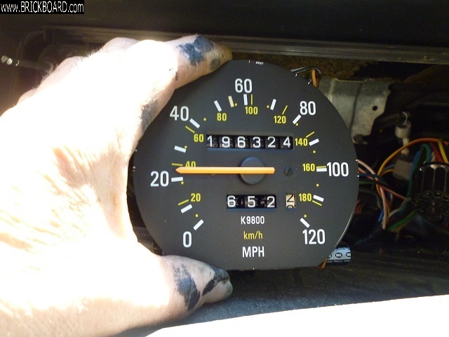
About half the time the needle will hit 0 and rebound instantaneously to speed. 30 miles in, it had done that twice, but at 50 miles it hit zero and stuck. And, yes, the odo stopped as well. So I tapped the dash as usual and nothing. Shutting down the car at home 150 miles later, there's been no more activity on either odo or speedo, so it looks like the fault is holding. Curiously, it's sitting at precisely 198 k.
I'd like to power it up on the bench and probe around but I'm not sure if I can do that. I have a spare L connector and the 90 wiring diagram I have shows the speed sensor wires, replaced by the AC adaptor I think, connected to the black and the green/white. If I powered it with a battery or battery charger, the positive would go to blue, but I' not sure about the negative and I'd rather not blow it up.
It worked remotely before with only 3 wires, so if I had to guess I'd say the black is ground for both the sensor and the 12V.
Perhaps there's a better approach than this, and I'm open to any.
regards, Peter
|
|
-
|
|
|
Hi Peter,
To me, the news that the two functions die together is good news. It means the cause is likely to be one we've seen before, not exotic.
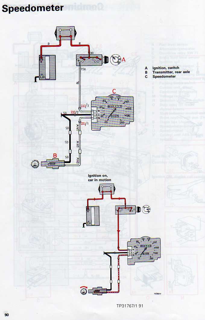
To isolate it while it is steady broken, one would use an ohmmeter at the L-plug looking back toward the speed sensor, measuring between the black and blue wires on the '87. That you have a green/white wire tells me you're looking at a later version wiring harness, for 1990 (airbag) cars and later. Bentley says you should see the resistance of a coil of wire in the range of 2950 ohms.
Intermittent as it is, fixing it by beating on the dash, you'd think this was a problem in the cluster, so I expect you will verify that speed sensor continuity. Given you've already been down the road with a substitute signal according to my diagnostic pictorial, I'd guess it isn't the L-shaped connector either, but one more lousy solder joint somewhere in the gauge itself. Try reflowing them all?
If you decide to run it on the bench, remember you need to add a jumper into the pin sockets to get the unit to power up. In the following picture, a plug like the one you have is being used on an earlier unit.
The black jumper wire completes the power path, but +12 is supplied to the blue wire on the L-plug, and ground to the black wire on the L-plug.
Disregard the red clip and resistor on the end pin-socket -- that was a means of checking the taximeter output for the cruise or LH2.4 VSS.
The signal substitution is applied to the green/white wire on this L-plug. What do you have to provide a signal on the bench? Without a purpose-made signal generator, you can use an AC-output wall wart transformer for 60Hz, or a tone generator app on a picturephone.
You might just jump to the chase scene skipping the science project by re-heating all the solder connections one by one, and then giving it a few hundred miles of real-world driving experience to test it.
--
Art Benstein near Baltimore
Don't find fault, find a remedy. (Henry Ford)
|
|
-
|
|
|
Hi Art,
I think it's very good news, a major breakthrough in the case.
That's a good idea to verify the car. It's unlikely, but possible that this shutdown was unrelated to the original fault. I've thrown a lot of numbers around here, so just to remind you - the cluster box is marked 1987 but the car is a 1991 non abs. So that means to test the resistance I would use the green/white and black, I believe.
I have a 7 volt AC output wall adapter. In fact, along with your Diagnostic, finding it in the free box at a yard sale was a part of the genesis of this enterprise.
Disregarding wire colors, the L connector has 3 parking spaces. One is separated from the others by a slot cut out of the CB. That's 12v. The middle one is ground, and the third is the speed signal. I think all 240 electro speedos are the same in this regard.
My AC adapter, like yours, has 2 wires. I used them to connect to the 2 wires from the black box in the rear of the car. If I use a battery for a 12v source, it requires 2 wires to complete a circuit. That's 4 wires with 3 parking spots, and that confuses me. I must be missing something because it only had the 3 wires from the L connector on it when it was running in my hand.
The middle black 'ground' on the L serves as the return path for the speed signal, but is it also the ground for the 12 volt battery ? If it is, and I now remove the battery from the car, the negative terminal will need to find a new path to complete the circuit. Do I just run a wire from the battery - to the middle ground spot on the circuit board?
I've studied the 2nd picture on Speedometer Notes and it looks like R to L there's 12v+, 12v-, and one signal wire. My 1990 wiring diagram shows both signal wires reaching the speedo.
I could just reflow everything, it might be less trouble, but it's winter and it's cold and I need to have fun things to do in the house. I was trained and worked for a few years in weld inspection, ASME code stuff, and there may be some of that left in me that wants to track down the culprit and bring him to justice.
Thanks Art. The info on the capacitors was very interesting to me . Every little bit helps.
Peter
|
|
-
|
|
|
Hi Peter,
It is my thick head and poor reading comprehension that caused me to lose track of the fact you're using the '91 (non-ABS) as a test platform to help fix up your gauge collection. Right, no need to re-verify the sender. Sorry.
"Disregarding wire colors, the L connector has 3 parking spaces. One is separated from the others by a slot cut out of the CB. That's 12v. The middle one is ground, and the third is the speed signal. I think all 240 electro speedos are the same in this regard."
Good analogy - the parking spaces. Good for the physical connector, but that middle one that is ground actually does get grounded in spite of what your '90 WDM shows, so it is providing the ground return for both the sender and the power from the battery. Couple motorcycles sharing the parking spot? The green book has errors in the detail pages that don't live up to the accuracy I find in the overall fold-out drawings at the end. I'll find some examples later and post them.
And, beginning in '92, the order of those three terminals changed. This even confused the draftsperson for the green book that year -- more errors. But the end result is you can't get the same signals if you interchange a 92/93 cluster with any other year. Designed that way, I think, because the gauge uses a different K-number or Kount of pulses per mile or km with the 48-slot tone ring. 91's with ABS have a separate converter, so they use the old wiring.
"The middle black 'ground' on the L serves as the return path for the speed signal, but is it also the ground for the 12 volt battery ? If it is, and I now remove the battery from the car, the negative terminal will need to find a new path to complete the circuit. Do I just run a wire from the battery - to the middle ground spot on the circuit board?"
If you're saying you use a battery on the bench to power the gauge, yes the negative post would connect to the ground terminal on the PCB edge connector -- the middle one on your '87 gauge, identified by the upside-down T which is the ground symbol over there. G stands for Gauge, and + for +12V. So you wind up with both ground wires in that middle parking space.
"I could just reflow everything, it might be less trouble, but it's winter and it's cold and I need to have fun things to do in the house. I was trained and worked for a few years in weld inspection, ASME code stuff, and there may be some of that left in me that wants to track down the culprit and bring him to justice. "
I'm happy to hear you are doing this for the learning. I had some welding training (two years) and along with the certification got a student membership to AWS. After 5 years of not being a student the dues jumped up so I dropped the AWS membership, but they still send me the emails and links to forum posts, most of which is centered around the inspection profession. It certainly was interesting, but I remain an outsider.
This detail from the '91 book looks right to me:

--
Art Benstein near Baltimore
By the time a man realizes that his father was right, he has a son who thinks he's wrong.
|
|
-
|
|
|
Hi Art,
Progress has been a little slow, but I thought I'd check in before this post becomes ancient history.
The complete failure of the speedo was unfortunately a broken wire at the diff. I remember fixing it about 10 years ago and found a dangling grommet on the cable which I couldn't find a home for. Looks like I Zip tied it to a convenient hole in the gas tank, not thinking that the tank and diff move independently. Since then I've found the rusted remnants of the grommet holder on other cars and replaced them with a stainless facsimile. I'll make another for the 91 in the spring. The original 91 box is in the car and happy.
I set up the 87 speedo indoors and brought in a battery charger for power. I've used it to test small motors before but it proved unsuitable for this job. Using the continuous charging rate knob, I could get varying speeds. At 22 mph it was only putting out 3 volts, and there was a slight vibration in the odo motor but no stepping. I noticed the 9 volt AC transformer was getting quite warm so I shut everything down. When I tried again the next morning with a battery, the transformer was dead and that put me back a couple of weeks until I could find another one.
All was well using the battery and new 12V AC source, but as happened when I tested it in car, I couldn't get it to fail with any amount of shaking. I let it run for a few days, about 500 miles, poking around it but it would not quit. Under ideal conditions with good light, I used a dental pick and forceps to pry and pull at every solder joint with the board loose and odo motor stepping, without getting any indications.
I had previously reported that I had looked at the main cluster circuit board but I think I'd confused it with another box. I always delete the temp fakir but this had not been done.This board is noticeably different than others I've seen. It has a different finish, almost like a polished wax, and is a darker green, and all the solder is gleaming bright. I don't know if it's a replacement or just the vintage. It has the larger wedge sockets for illumination. Do you know when they changed to the smaller red/brown type?
I checked the ribbon fuse, but I did find the speedo pin sockets to be fairly wide. I bent the arms in until they were touching. A bad contact there would explain why a gentle tap on the dash would bring it back to life, I think.
It's together and ready to test, but the sap's about to run so it might be a bit before I can do that. If it fails I'll try to see what else besides the speedo is out. I'm not sure if everything on the cluster gets it's power from the L connector or not, so that might be of interest.
regards, Peter
|
|
-
|
|
|
Don't be concerned about becoming ancient history here. RWD Volvos are in that category to begin with.
Part of that history are the changes that occurred every year in the instrument panel made by VDO for the US market 240. The lamps providing the backlighting for the gauges changed from ordinary incandescent-in-vacuum lamps (brown base) to the pricey incandescent halogen-filled 3-watt lamps (reddish base) with the 1989 model year. All clusters I've seen have a date somewhere stamped indicating date of manufacture, e.g. Sept. 1988 might be part of an 89 model year car.
The features are known distinguishing each year's change from each other, but I only know about function (fit, form, function) and cannot pass any good info along on finish, such as circuit board coatings, or whether the gauge metal is painted with matte or satin black except to note the 86-88 are supposed to be satin finish.
Sounds like you've fully tested that 87 cluster. Strange why the 9VAC transformer cooked itself to death. Finding an AC-to-AC adapter isn't easy these days, and I notice the wall warts have "AC Adaptor" on their nameplates meaning they adapt your "device" to the AC in the wall outlet, not that they provide AC output.
Battery chargers come in all sorts of sizes and designs. Some provide only current limiting. Some provide pulsed output depending on terminal voltage. They aren't, as a class, good general purpose power sources. They are battery chargers. The cluster is indeed powered through that L connector on the speedometer, meaning all the warning lamps and the gauges and their stabilizer. It needs a steady, clean voltage supply, as from a battery, or purpose-made DC source. I have a small AGM (gel cell) battery on the workbench, such as is used for kids' toy cars, to use testing 12V car things.
March is coming rather quickly this year.
--
Art Benstein near Baltimore
What engineers say and what they mean by it:
Engineering says: "The entire concept will have to be abandoned"
Engineers meant: The only guy who understood the thing quit.
|
|
-
|
|
|
Hi Art,
I've had the offending cluster in for a week which included an 85 mile trip on a pot-holed, heaving, 2 lane paved road, and not so much as a hick up out of the speedo.
I think it's safe to say that tightening up the pin sockets was the cure because that's the only thing that I did. Deliberately, at least.
Do you have any idea why there's an O in what could be called a speed meter ? We have water meters, hour meters, amp meters and such, but none have an O. I thought it might have something to do with matching up with odometer, but it seems that 'odo' means road in Greek, so I don't think anything's added.
Thanks for the help. Peter
|
|
-
|
|
|
Our old cars are chock full of electrical connections most of which have survived and continue to provide that metal-to-metal contact sufficient to maintain their original purpose. Each of them depends on physical force or tension keeping those separate metal objects in touch well enough to exclude insulating oxides and chemistry intruding from the moist environment. Some of us love to critique the engineers who pulled them all together, or the accountants who made them affordable, while I just remain amazed.
The mystery of the O is one I previously gave no more thought to than dismissing it as a brand name-turned-generic like if we called bathroom scales Health-O-Meters. You out-curioused me on that one, Peter. https://www.etymonline.com/word/speedometer
I do remember helping someone in France, where he referred to this same device as a tachometer (not compteur de vitesse), which I believe is how Germans call the device they don't need on the Autobahn. Can be confusing to those of us who refer to the "rev counter" as a tachometer.
--
Art Benstein near Baltimore
"This article may be too technical for most readers to understand. Please help improve it to make it understandable to non-experts, without removing the technical details."
|
|
-
|
|
|
Great Art, that's exactly what I needed to know.
You also explained why the spare L connector with pigtails that I snipped out of a 92, and planned to use, had the green/white and black reversed from their positions in the 91. I thought I or someone else had monkeyed with it. I swapped them over in case I forget.
I'll let you know how it goes.
Peter
|
|
-
|
|
|
Hello Peter,
I don't have a useful reply to your post, just a reflection. My 1992 960 had been sitting for over a year when I bought it and the speedometer did not work for at least the first fifty to a hundred kilometres of driving.
Then it began to jump up and then back to zero for a while. And then it just began to fully work. I don't have any explanation for this but it would appear the Volvo gods woke up with all the stimulation and everything got back in order. Now it is steady and reliable.
But I know that if I leave it sit for a while the gods will be displeased once more.
Bob
|
|
|
|
|
