|
|
|
Hello all
I have a question about the ect circuit on '92 240 LH2.4
Will impedance on the grounds to firewall and side of block cause a new ect to not function properly (no sliding resistance in relation to engine temperature per scale in Bentley manual)?
Thanks
|
|

|
|
The ground from the side of the block to the battery negative is important, but for a whole lot more than just the sensor reference which gets there through the sensor body to head, head to block through head bolts. If you had high resistance there, it would show up first trying to crank the motor, but worth checking.
The firewall to cam cover ground is not needed except to reduce radio interference.
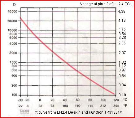
Measure the voltage at the ECU connector as the motor warms up, and match it to this chart rather than trusting your ohmmeter skills.
--
Art Benstein near Baltimore
"If you don't know where you are going, you will wind up somewhere else." -- Yogi Berra
|
|
|
|
|
Have checked voltage at #13 and voltage hasn't gone lower than 4.2 volts.
Ect is Uru brand from FCP (actuality replaced it another to eliminate bad new sensor)
Continuity/voltage to sensor plug-in checks good
Cleaned the plug-in with contact cleaner and made sure pins seated properly
|
|
|
|
|
Hi,
Maybe I'm missing something here!
That voltage up to 4.2 is totally a wrong reading at the ECU pin 13.
It seems that you are checking the ECT connector out at the engine?
That would be applied voltage coming to the ECT from the ECU.
The chart is the readings with the resistance of the ECU applied "in circuit" across the pin #13 to ground.
Doing it this way you are checking everything. The ECT and all the wiring too and from the engine.
Are you sitting at the back of the ECU with the rear cover off?
You need to back probe the terminal block @ pin #13 while it's all connected up.
According to the chart or graph, that Art provided, it's saying the temperature is zero degrees or less.
In normal "sweat shirt" temperatures of 50 to 75 degrees the voltage is meant to be in the upper 2.0 volts range.
A lower reading will happen if the engine is warmer.
With the engine up to operating temperature (92C to 87C) it should be .5 V to .3 volts.
With the key on or even the engine running, the red lead of the Voltage meter, is put in the socket of the proper color of the #13 wire and the other lead to a good ground point on the body of the car or ECU chassis.
You either have the sensor disconnected from the sensor while reading at the ECU or that sensor is bad or wiring no matter how much you clean the connection pins.
When you are talking about grounding of the ECT in the head, you do not want to use any kind of thread sealant, as that will insulate the ECT from having a good ground!
The threads should be of taper lock design and should not leak.
There is a "slight" misnomer about thread sealants tapes (Teflon) and compounds when it comes to these type of threads.
It does not seal them but lubricants the threads so they will tighten in easier or make a smoother engagement.
Especially, if the two materials of the mating are the same or alike to prevent galding!
The threads need to be made with good sharp taps and dies so no tearing of the thread lands or faces occur.
If the depths of the two threads are made correctly on each part, they should work dry as their design name implies, "dry seal threads" and tighten appropriately.
The British actually dealt with this in the early years of modern aircraft design. Probably around WWI or II. Or as I suspect the advent of jet engine racing.
They called it a "gas" thread! BSPT or BS or BSPP for straight pipe threads.
Our NPT system is a copy, even though, I have not research this!
I taught it or made statements, in my classes, as we probably "stole the ideas" by changing it slightly somewhere along during the war lines.
It helped keep the students more awake "thinking" that "we" could do such a thing! (:-)
Edit: I found this out of curiosity and running my mouth, again!
https://www.ralstoninst.com/news/story/the-difference-between-npt-bspp-and-bspt-seals
Phil
|
|
|
|
|
I am backprobing @ #13 with ecu still connected and a good ground w/black lead, operating temperature with key in run position.
No sealants used in ect sensor install
My question was would impedance at block ground basically render the ect sensor inoperable thus giving me a voltage reading with minimal resistance?
Or if the block ground I'd bad (side of block), will the voltage be zero @ 13 with same circumstances as above.
|
|
|
|
|
"My question was would impedance at block ground basically render the ect sensor inoperable thus giving me a voltage reading with minimal resistance?"
No
"Or if the block ground I'd bad (side of block), will the voltage be zero @ 13 with same circumstances as above. "
No
My question to you was a request that you verify my understanding of how you checked the wiring from the ECU to the sensor in more than 6 words. Once I went round and round for hours trying to help a guy trace this circuit before learning he was measuring pin 13 on the wrong computer. Six words don't always bridge the gap. Seeing 4.2V at pin 13 with the sensor connected says the sensor is open circuit, wrong type, or the wiring is not really connected.
--
Art Benstein near Baltimore
Sometimes, the good you do does you no good. -Dr. Phil's way of saying no good deed goes unpunished.
|
|
|
|
|
Red lead of voltmeter backprobing @ #13 of "white label 561" ecu seated plug/harness whilst vehicle ignition is in run position and at operating temperature (192 degree thermostat) .
Black lead of voltmeter contacting good ground on firewall.
|
|
|
|
|
Dear SBP,
Lets try this again, please...
Last Thursday you said "Continuity/voltage to sensor plug-in checks good"
My question to you was this:
This statement means to me "I pulled the connector from the sensor and measured the voltage between battery negative and the connector's female pin where the blue/red wire connects, and found 4.2V, same as measured at the ECU with the sensor connected and installed."
Is that correct?
I'm trying to learn, in detail, how you know the wiring to the sensor "checks good" because obviously, to me anyhow, it isn't or the sensor is NG. The questions about "ground impedance" are red herring.
You said:
"Red lead of voltmeter backprobing @ #13 of "white label 561" ecu seated plug/harness whilst vehicle ignition is in run position and at operating temperature (192 degree thermostat) .
Black lead of voltmeter contacting good ground on firewall. "
We know this already. It was well described by you before. You said you read 4.2V at pin 13. I told you the circuit to the sensor is open.
--
Art Benstein near Baltimore
How to Ask Smart Questions
|
|
|
|
|
Art
The question of ground impedance to you is a red herring, to the person asking it isn't. Thus the question.
You asked me to describe in more than 6 words how I made a reading @ #13. So I did.
|
|
|
|
|
Hi Steven,
I see that you might be getting a little frustrated with your cars wiring or the sensor.
This is a two way street of communications of which has plagued the world for centuries. Knowing what you said or what you thought you were saying and the flip side is on how it was heard in the other persons mind!
We are lucky at the moment we are not translating on top of that!
I would not get onto Art Bernstein case about ring to the point and wanting clarity of how you are using the leads of your meter and where you are putting them.
There are circumstances that the meter can show you that will be the same numerically but mean what?
That is the “cute” in all of this!
Depending on what mode the meter is in or how you apply the connectors onto or in-line with a circuit will rolls up the sleeves and tighten the thinking caps!
You used a technical word called “impedance” which in itself pertains to an Alternating powered Circuit of electricity. We are using DC not AC.
You can also use terms like reactance, susceptance, reluctance, inductance and they will get you in big trouble with someone who understands it.
I can try to tell you electricity is simpler than electronics because you don’t have to think so deeply about it. What you need to do is just float on top.
If the world population had to learn about electronic theories first, in order to have babies, there would be a whole lot less people on this planet!
First of all, A man and woman having sex has its own electricity but electronics is a study of something like DNA. It’s a whole lot smaller world in there!
This testing and thinking about it’s impedance getting on the brain really doesn’t fit into the mechanics of this application.
This word alone raised up his antennas to what you are doing to get that high a voltage input to the meter if you looked at the chart.
In fact, the voltage plus the buzz work didn’t fit! So, it did the same to me that made me post the earlier comment in this thread.
I was suspicious that you were on the sensor end, out under the hood, doing a measurement without the sensor connected. Reading the output from the ECU to the sensor. A lot of things working only on 5 volts.
In this case you were reading 4 volts because you made a good enough ground on one half of the wiring to get that voltage. It was coming out there on one of two wires. He is asking where the probes were! Both leads In the connector that fits the ECT sensor or only one? It is a tight fit in that fitting.
Outside or inside the car and where about was the sensor, as I was also thinking!
On the other hand, if you were reading at the ECU inside and got a good ground.
You still may not even be reading the sensor, if a ground wire has broken. This being on the grounding side going out to there!
It would be the same as having no sensor hanging in out there!
I went thinking the body of the sensor got insulated.
Do you get it now? Possible open circuit on the ground wire! The location of the leads matter!
You see, you got to be “a little smarter than the meter!”
A soul can be grounded in more ways than one! Same for a meter!
Most of the time, during a week a meter knows what its doing!
But it can be just as dumb, as two ways from Sunday, on which day of a weekend starts or ends a week!
Some even say it’s Monday, since you are to be forgiven on Sunday, unless you’re retired, then it doesn’t matter so much! (-:)
It takes a “human” to figure out whichever is important, as this apparatus is human built with various limitations of capabilities.
We make machines to be better than ourselves and prove it everyday, that “perfect” cannot exist, but perfecting is always a work in progress!
If you had read the 2 plus volts at the ECU, per the chart, with the sensor in place with a complete circuit, we wouldn’t be having this conversation.
The ECU tells all! It has to COMMUNICATE on a two wire street in this case.
This sensor has two wires, where an oil switch and most temperature sensors only have one and uses a chassis ground!
This one has to be made to work with a more sophisticated and sensitive circuit than heating up a bi-metal strip for a temperature gauge in the instrument cluster. It’s only a reference to about H to C or about E to F with lots of blank space in between!
I hope this cooled the waters of anxiety and you don’t tick off Art!
He had kids, that I bet he took good care of them to learn things and besides he takes a lot of his time to help us!
There is some real good technical stuff in his soul!
A live, thinking, Bentley manual he is!
I didn’t have kids, as I’m still trying to figure out electronics.
I have a good grasp on electricity but maybe I’m just a backwards child!
(-:)(:-)
Phil
|
|
|
|
|
Phil,
You're right, he's frustrated. Been chasing this since November, and reading comprehension challenges aside, there's a third party in the mix who isn't part of these threads.
At first, when the 4.2V was reported, I thought he was quite close to solving the trouble, if only I could get clear and honest answers to a couple questions. The reading he took is clear evidence the circuit to and through the sensor is wide open. Very simple. If you want to test this for yourself, pull the connector off of the ECT sensor on your LH2.4 car, and measure the voltage at pin 13. You'll see 4.2V.
I think I just rub him the wrong way. Read this thread, you'll see.
https://www.brickboard.com/RWD/volvo/1659539/220/240/260/280/engine_temperature_check_sensor_cold_start_problem.html
--
Art Benstein near Baltimore
"I been in the right trip but I must have used the wrong car." -Dr John
|
|
|
|
|
Phil and Art,
I appreciate the help you've provided and yes this has been a frustrating endeavor.
Yes, Art, you do "rub me the wrong way" .
|
|
|
|
|
"Continuity/voltage to sensor plug-in checks good"
This statement means to me "I pulled the connector from the sensor and measured the voltage between battery negative and the connector's female pin where the blue/red wire connects, and found 4.2V, same as measured at the ECU with the sensor connected and installed."
Pins inspected and cleaned, making sure they lock into the housing is a must.
"Ect is Uru brand from FCP (actuality replaced it another to eliminate bad new sensor)"
Brand doesn't help me nor does it sound familiar. More important would be some assurance you have the correct sensor. The Bosch sensor has a black body. It would show a room temperature resistance of about 2000 ohms measured between its brass threads and either pin.

--
Art Benstein near Baltimore
Impedance is complex. Resistance is real. - AB
|
|
|
|
|
