|
|
|
Hello all,
Some electrical gremlins have recently popped up in my 93 244. I've previously had bouncing speedo problems solved by plugging in the 3-pin L plug when it comes loose, but in this case my speedo is bouncing and the ABS light comes on and stays on after reaching something like 5 mph.
Things I've tried, to no avail:
- Reflowing solder on the original speedo (K40168)
- Retensioning pins in 3-pin L plug
- Swapping a different speedo from the same year (K39200)
- Swapping the rear diff speed sensor with one from a 940
I tested a speedo from a 91 (k1xxxx) which had smooth motion but with a higher than normal speed. The stock k40168 speedo will usually seem fine until 20mph, or may bounce erratically. The motion is definitely unpredictable.
It could be that the sensor and k39200 speedo were also bad. Next in line is trying a new rear diff sensor, although I am certainly open to suggestions.
Does this sound familiar to anyone?
|
|
|
|
|
I just posted ~ 2 weeks ago about something similar.
On my 90 the speedo and odo always quit together. It'd work for 1 mile, quit, come back with some dash taps; then it might work for 5 miles or 200 ....
Bumps on rough roads seemed to precipitate it.
did what you did
- Reflowing solder on the original speedo
- Retensioning pins in 3-pin L plug
What I noticed was that the strips where the 3-prong L-shaped prongs touch were worn in the center. I believe they were worn through by the prongs being loose and rubbing.
I'll try to take a pic but I don't have a camera with that kind of resolution.
I finally replaced the head with another old one and it's worked fine now for 1000+ miles.
--
240 drivers / parts cars - JH, Ohio
|
|
|
|
|
I'm slowly going insane!!
I've done and been doing some HARDCORE troubleshooting. Greenbook pdfs, dissassembly, and all.
To remind what's happening:
ABS light comes on at around 5 mph, speedometer goes to around 20 and does not increase.
I have:
-Swapped rear speed sensors from 2 donor cars and a new Bosch part
-Swapped clusters with 2, one known working - all show the same symptoms
-Swapped ABS modules, ABS overvoltage relay, ECU/EZK from 2 other 93 244s
-Cleaned almost every single ground connection and plug connection with contact cleaner, added dielectric grease (not for the connectors!)
-Replaced plug near VSS
-Ran an entirely separate wiring harness from a junkyard car (tested continuity from sensor to white plug end)
-Swapped ABS hydraulic module relays (pump and solenoid relay)
-Cleaned ignition switch pins
-Cleaned fuse holders and fuses
And yet, this powerful electric gremlin persists. The only other thing I can think of is that maybe the ABS hydraulic module is faulty and needs to be replaced. The 700 series ABS brake diagnostics document lists the above symptoms as sensor or pump related, and I believe I've ruled out the sensor. However, it doesn't seem like the pump and speedo should be related...
<:(
|
|
|
|
|
Art,
The speedo does not work with the module unplugged.
|
|

|
|
"The speedo does not work with the module unplugged. "
Message is too short.
--
Art Benstein near Baltimore
If you think nobody cares if you're alive, try missing a couple of car payments.
|
|
|
|
|
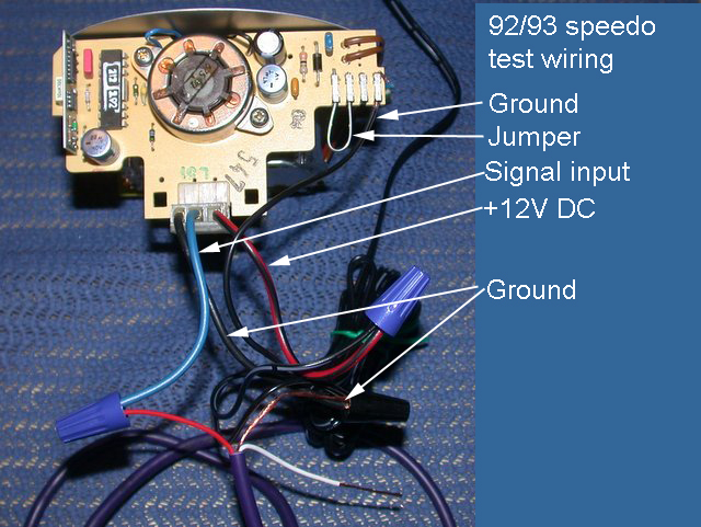
This is for the load testing. The speedometer does not work with the ABS control module unplugged - do the speedo signal wires (green, black) need to be tied to ground if the module is unplugged?
As I mentioned before, two green/white wires run out of the white plug behind the knee bolster. I assume one goes up to the cluster wiring, the other to the module.
|
|
|
|
|
OK, I get it now. The speedometer worked somewhat until you unplugged the ABS controller, then it didn't work at all.
Sorry, you are absolutely right. The ABS controller is providing the ground reference to the sensor. My suggestion was bogus.
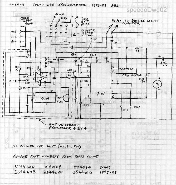
This is a drawing from the '92 book. I have a pdf from the late production '93 to compare with, and nothing pertinent to the ABS sensors or speedometer connection is different, just differences related to the move of the fuses to the engine compartment.
To do that check of the ABS loading, you'd have to unpin the green/white at 7 on its connector, I think, or supply a jumper to ground reference. Not as easy as pulling the plug like I thought previously. That's a long shot anyway, unless the module took on water. On second thought, it might be worth it to unplug the ABS and just add a jumper back at the rear of the car to the black wire grounding it there, just in case the ground provided by the ABS module is what's awry.


--
Art Benstein near Baltimore
Before you criticize someone, you should walk a mile in his shoes. That way, when you criticize him, you're a mile away and you have his shoes.
|
|
|
|
|
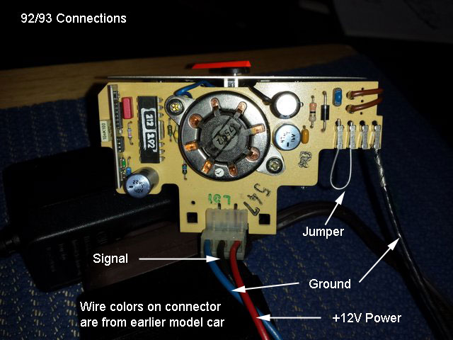
Here's the white block connector behind the knee bolster I was talking about.
The two green/white wires come out the top, to the gauge and presumably the ABS unit.
Funnily enough, my it seems like older 240s had the speed sensor gauge wiring harness go to a connector in the trunk. In 93s, this harness goes straight up to the front with no disconnects.. This seems to me like a terrible idea for maintainability. Do you recommend splitting this up with some male/female connectors?
In the interest of being thorough, I'm wondering if I should measure the sensor's resistance with a meter - maybe my patch job on the harness was not done well. I elected to solder them on. Do you know any expected values for resistance?
Best,
David

|
|
|
|
|
"Here's the white block connector behind the knee bolster I was talking about.
The two green/white wires come out the top, to the gauge and presumably the ABS unit."
David, thanks for the clear photo. Very clear to me this isn't an enthusiast's modification. Learning it is behind the knee bolster helps me to come to the same conclusion you have about which one it is in the wiring diagram, and then wonder why you found another 93 didn't have this. Am I correct to remember it was indeed a 93? The 91, with optional ABS, was wired differently.
"In 93s, this harness goes straight up to the front with no disconnects.. This seems to me like a terrible idea for maintainability. Do you recommend splitting this up with some male/female connectors?"
I agree with you, but I don't know from experience that in '93 Volvo dropped the use of the high-strand-count silicone rubber insulated flexible cable between the sensor on the diff and the junction box inside the body. However, I've been surprised by so many things I've found and heard reported by others in 93's. I picture the assembly floor in around March or April of 1993 to have been more like a team of MacGyvers than a boring mass production line, digging up substitutes for all those parts that ran out before the bodies did. I'll have a look in my daughter's '93 next time, maybe when I have a rear wheel up to check for the presence of the notched brake caliper piston. Recommend? Unless you can duplicate the longevity purpose of that flexible cable, why bother?
"In the interest of being thorough, I'm wondering if I should measure the sensor's resistance with a meter - maybe my patch job on the harness was not done well. I elected to solder them on. Do you know any expected values for resistance?"
Absolutely. Bentley shows the sensor's response to an ohmmeter should be from 600 to 1600 ohms (p.380-2). I can understand a wide range to account for temperature, but that range sounds ridiculous, as if accounting for different reluctor vendors. Anyway, I'm sure you could check the resistance at the sender, and look for the same reading up at that connector you pictured, the wiring being a negligible addition with respect to the winding in the sensor. But you already swapped the sensor and the cable, so again, I'm puzzled. Bentley also has a table on sender specs in the rear axle section, p.460-4, with a mention of a 96-tooth* tone wheel (impulse wheel or gear) which adds to my puzzlement. Could be another candidate for red pen, but I don't know.
*I've only seen 12 (non ABS) and 48 (ABS)
--
Art Benstein near Baltimore
The journey of a thousand miles begins with a broken fan belt and leaky tire.
|
|
|
|
|
Art,
Strange happenings!! Resistance measured at 3 pin cable is 1200 ohm at key in KP 0 and 1. At KP 2 and 3, however, the resistance goes up to 2900!! I cleaned the contacts in the ignition switch previously so I don’t think it’s that, which is in circuit.
|
|
|
|
|
Not strange. Resistance is never measured on powered circuits.
--
Art Benstein near Baltimore
"Carefully pry (If this were a Jaguar you would prise)..." -BrickDad
|
|
|
|
|
This is a very persistent bug. I fear I might have brought some bad voodoo upon my car...
As part of my shotgun diagnosis I will go in the engine bay and clean connectors that have a black wire that may be a ground - one wire sleeve goes into the cab from the passenger's side where the ECU/EZK and ABS module are.
It may also be worth noting that my brake light is coming on when my lights are fine. The failure detection relay looks pretty crusty inside.
Besides that, I'm as puzzled as you are - the impedance is in the correct range, and reading the sensor on ACV shows good motion to about 4 ACV - it may go higher, but I have not done this test in a place where I could go above 30mph. I still suspect this has something to do with a ground on the ABS side. Is there something I can probe on the ABS module connector that might be enlightening?
Thanks for your continued help.
|
|
|
|
|
Sure. Like I suggested before, add a temporary jumper between the black wire from the sensor and ground. Check continuity to ground. I expect I'd do it right from that connector you show in your picture.
Trusting communication of AC voltage readings over the internet with unknown equipment can be dicey, especially if you're the sort who uses a meter that way maybe once a year. But 4V AC is plenty to drive the speedometer.
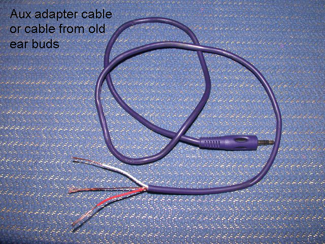
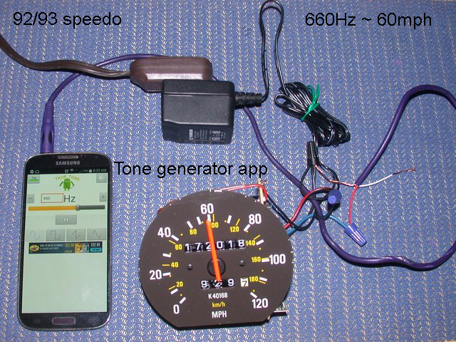
You could also try what I suggested earlier and substitute a signal from a tone generator app, if you don't have test equipment you're familiar with. Worth a try for the price of an old earbud cord.
Lots of angles to pursue here.
--
Art Benstein near Baltimore
Expert: An "ex" is a has-been and a "spurt" is a little drip under pressure.
|
|
|
|
|
Art,
I went to my car to to the speedo test with the TRS connector, and I noticed that the ground and signal wires were switched. This may have happened when the speedo cut out on one of my interstate trips and I adjusted the tension on the connector, and would explain why the 91 cluster worked without modification.
Everything is fine...
May God forgive me.
|
|
|
|
|
David,
Perfect explanation covering all the mysteries! Thanks for posting back.
--
Art Benstein near Baltimore
A three-legged dog walks into a saloon in the Old West. He slides up to the bar and announces: "I'm looking for the man who shot my paw."
|
|
|
|
|
Art,
First of all thanks for the quick reply and useful diagnostics. Your website and posts are top notch. I didn’t change any pinouts on the 91 cluster, but my other k4xxxx clusters show the same symptoms.
As far as load, I did see something suspicious when inspecting the wiring. The harness from sensor to the front goes through a white 5 pin block. The green/white wire was tapped off twice - one goes up the harness to the speedo, presumably, and the other I have no idea. When I ripped the harness from the 93 junkyard car, I didn’t see this.
I have access to an oscilloscope and dc power supply. Tommorow I will get back to you with a test on one of the speedo heads I have.
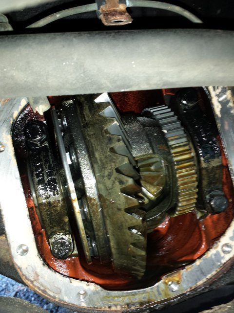
I would like to open the rear differential some point and see what’s up with the tone ring.
|
|
|
|
|
"As far as load, I did see something suspicious when inspecting the wiring. The harness from sensor to the front goes through a white 5 pin block."
Along with your ability to swap in a 91 cluster, this is a mystery that deserves pursuing. Maybe you can provide more detail; e.g. location or photo, or isolate the two to see which one or if both are necessary for function. Did you get your car from an enthusiast?
--
Art Benstein near Baltimore
Everyone seems normal until you get to know them.
|
|
|
|
|