
|
|
Hi,
I was sent here by ACT1292 from the volvo forums and I was told to ask for ART.
I bought my 85 244 without the gas gauge working about a year and a half ago. I have been working with my gauges, testing my voltage stabilizer, and working on the cluster the last few weeks. Anyway, the other day I was checking voltage on my 32 and 31 cluster wiring not realizing I had my multimeter in the 10V section. Well of course it sparked a little while touching the probe and then my idiot lights flashed a few times and I have now lost power to my cluster. My cluster night lights come on but it is my understanding they are run through a different system than the idiot lights, etc.
After the incident I tested my voltage stabilizer and I am getting no voltage on anything. The circuit board doesn't smell burnt and no resistors appear to be blown. Also, during the incident, no smoking or such occurred. I have also lost all function of my turn signals as apparently they are powered through the cluster as well. I would like to get this taken care of and I feel the issue is power source related. I do have hazards and all fuses are clean and giving off well over 12V.
Any help would be appreciated,
Thanks
|
|
-
|
|
|
When you mean ground the wire what are you referring to?
Also, how am I suppose to test the circuit board foils while plugged in? Will I literally take the cluster apart and then attach the connectors to the circuit board alone and test with multi-meter?
Lastly,
I have connected everything back together and both gauges are not working now. The temp sensor wire looks pretty crusty down there but the temp gauge gas always worked. When I placed it back together I put the gauge in, placed the washer down, then the cylindrical copper piece, and then the nut. Is this correct? I still have my speedo disconnected because the previous owner broke the plastic locking piece. I have to figure out how to get that cable re attached but will my speedo being disconnected affect the gauges at all?
Thanks
|
|
-
|
|
|
Would I test resistance at the cluster gray wire when plugged up?
Could you also expand on the following the circuit board for resistance? Were you talking about resistance or voltage?
Also, I guess I over looked some things today as well :/
My #13 fuse was blown right in half. I don't know how I did not catch that!!!
So now I should have power to my cluster. I honestly was just going to rip that gray wire out and run a new wire from the semi circular connector to the trunk just to rule out any wiring harness issues.
Thanks!!!
|
|
-
|
|
|
Well ART,
Its been fun. I believe putting a new fuse in will give me power back to my cluster and honestly I have been inside and outside of this cluster for the last few weeks so I should be able to get my fuel gauge working. If I end up running into anymore issues I will start a new thread on this here brickboard.
Happy Bricking,
Travis K.
|
|
-

|
|
Sure.
To sum up, ground that gray wire at the cluster. If the gauge responds and goes to full, you've vindicated the indicator. If not, you might have something like a fine crack in the circuit board -- too fine to be resolved by your photography, and you'll have to use your voltmeter to trace where the 10V goes to zero.
If the gauge does work from up there, repeat the grounding back at the connector to the fuel pump/sender assembly. Same gray wire. Ground it and the gauge should go to full. If it doesn't, then go to extremes like running a long wire to replace it. Consider this especially if you have a lot of rust.
--
Art Benstein near Baltimore
When an actress saw her first strands of gray hair she thought she'd dye.
|
|
-
|
|
|
Use your voltmeter to trace voltage with the power on. Use the ohmmeter to measure resistance in un-powered circuits. Don't use the ammeter function until you master the other two uses.
--
Art Benstein near Baltimore
Those who get too big for their britches will be exposed in the end.
|
|
-
|
|
|
OK,
So resistance on my temp gauge is 0.05.
Resistance on my fuel gauge is 0.05 as well.
This is on the 20K setting. on the 2000 setting I get:
TEMP-051
FUEL-050
|
|
-
|
|
|
Good. Seems like the gauge is not at fault.
Next step is to repeat that test at the gray wire, measuring voltage with key on, assuming you've fixed the problem keeping power from getting to the cluster. If you still see zero there, move your voltmeter probe back toward the source, following the foil trace to the gauge terminals.
The theory is, you'll find where the zero turns to 10V. That will be where the fault is.
--
Art Benstein near Baltimore
Acupuncture is a jab well done.
|
|
-
|
|
|
Still unsure how to respond directly to your post.
I already checked voltage on the gray wire when cluster was working last week. I got 0 for voltage at cluster gray wire pin while cluster was on and connected. Voltage was coming off the stabilizer. 12.38, 9.96 I believe. The battery light wire (blue/red) was giving off over 12V and the brown wire (parking brake switch) was giving off like 2.68 set.
So I believe the issue may be in the harness. I also replaced the old sending unit with one from a 92 so I do not believe that is the culprit. I also got 0 at the sending unit connector for the gray wire.
My gas gauge has jumped before and worked for a few seconds in the past.
Thanks.
|
|
-
|
|
|
Ok, I just thought of something you can do with the cluster apart. Use your multimeter to check resistance. Check the resistance between the gauge terminals with the gauge not installed on the circuit board. Compare it to the temp gauge.
If you are still unsure, you can swap the two gauges, I think, just to see if you move the problem from fuel to temp. Anyhow, the gauge is seldom open circuit, but it does happen; there's tiny wire inside with fragile connections.
Just be sure it wasn't simply loose nuts.
--
Art Benstein near Baltimore
We can complain because rose bushes have thorns, or rejoice because thorn bushes have roses. -Abraham Lincoln
|
|
-
|
|
|
ART,
I will gladly put the cluster back together and recheck on fuse 13. I have the good quality fuses so cleaning those tabs and putting in a fresh fuse is no problem.
Are you sure that the black/brown area near the half circle connectors is no big deal? There is definitely plenty of flux hanging around the board but if you say you see no problems then I will go with it. I also took my alternator to the shop just to be sure but it tested fine. When you say the blue/red wire you are talking about the alternator wire correct? I have studied the diagrams some. But driving with my cluster disconnected is no longer keeping the car charged so I need get this fixed asap.
I will check back after fuse 13 clean and replace.
Thanks
|
|
-
|
|
|
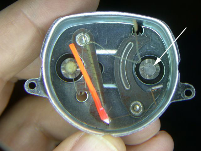
xD, I do not see anything in your pics looking like the destruction from an inadvertent short circuit. At first I was going to have you put an arrow in pointing out what you suspected, as pin 4 on the 6-pin connector is a ground (black wire) and on the 12-pin connector, pin 4 is the 5th gear indicator. The "half moon" description tends to be ambiguous, because the semi-circular 6-pin plug has been called that, as well as the 12 pin plug with the semi-circular keyway in the center.
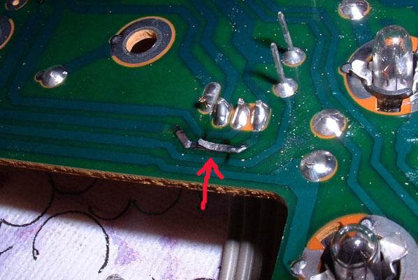
Here's what the typical damage would look like:
If you notice the gray wire on the 6-pin plug, in position 1, that's the fuel gauge wire. With the cluster all plugged in and resting atop your steering column cover, you could check for 10V there before re-installing the cluster. Key in KP-II. If you have 10V, you know the problem is at the other end, at the sender or between. If you momentarily ground that pin, say, using a paper clip to bridge between the gray wire and the black wire on the opposite end of that 6-pin plug, the gauge should go to full. If that works for you, there's nothing more to do with the cluster removed. If it doesn't, start a new thread. Otherwise install the panel, and fix the fuel gauge on the sender end.
The blue/red is the color of the wire getting the power from fuse 13 to the cluster. The wire is most likely OK, but you might have to get like a dental hygienist and pick the tartar out of the fuse holder's dimples. Best thing that can happen from all this is you get some useful experience with a multimeter.
Please use the reply to link from this post, or I get no notification you've updated the thread, so I won't see it unless I check it out by chance. By the way, act1292 is giving you excellent help in your other thread. Better than I have.
--
Art Benstein near Baltimore
Marathon runners with bad footwear suffer the agony of defeat.
|
|
-
|
|
|
HEY ART,
Sorry for the bad link. Here is a new one that should work.
https://postimg.org/gallery/2ceoo63gq/
If you take a look at the half moon solder joints one of the tracings around the joint is burnt. I believe this is my culprit. However, since it is not just a tracing away from joints, can I still connect a wire on a good trace and then connect directly to the solder joint itself? Also, will the burning around the joint still affect the new bridge?
Please let me know if all else looks normal
Thanks so much
|
|
-
|
|
|
Sorry I left out that vital information.
My front signals went first and then recently all signals have gone.
Thanks
|
|
-
|
|
|
No, you didn't leave it out. You told me in your original post, I just failed to read it carefully. Because of that, I offered the wrong advice.
I'm sorry I steered you to the work of tearing apart your instrument panel, but thankfully I was wrong, and you don't need to fix your circuit board quite yet.
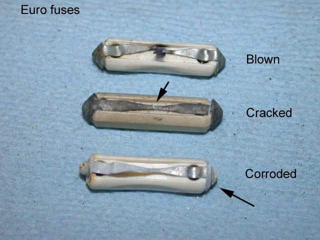
The problem is almost certainly at fuse 13. Going over your post on VolvoForums I see you had looked at this already, seeing 12V or more on the output of the fuses.
Double check that number 13. If the fuse itself isn't cracked or broken, it might just be crusty. Anyhow, if you can't make the turn signals work, there's no power even getting to the cluster, so that blue/red wire may need to be looked at.
Usually the weak spot is the circuit foil; even weaker than the 8A fuse, so that's what gives up. But in your case, I bet the weak spot was corrosion on the end of the fuse. I couldn't see any problem in your photos, so I have to assume you see some old crusty flux at the connector's solder pads as a result of me sending you on that wild goose chase.
Once you get the power back to the turn signals, the cluster will probably come back to life. What killed it (sparks) is using the multimeter in the current (amps) mode by connecting the probe to the 10A socket (not 10V). That makes your probes a virtual short circuit. Current needs to be measured in series with a load.
After getting the cluster working again, start a new thread on the fuel gauge. It might be the gauge itself, but there are some simple tests we can make to prove where the fault lies.
--
Art Benstein near Baltimore
No trees were harmed in the posting of this message...however an extraordinarily large number of electrons were horribly inconvenienced.
|
|
-
|
|
|
You said the hazards work.
Answer this question: Do your turn signals work?
--
Art Benstein near Baltimore
Beauty is only a light switch away.
|
|
-
|
|
|
OK,
ART or SOMEONE PLEASE!
Here are the pictures of my board. On the 4 pin half moon connector you can see the track appears black/brown and burnt. Could this be the culprit?
The soldering at the full circle connector area looks pretty dirty and dark as well. Is there any way to repair this or should I order a new board?
My alternator went out as of tonight and won't keep charge. I believe it may be from this cluster not having power. It is my understanding the battery light actually helps keep the system charged. I need to fix this asap so I can get this 244 on the road again!!!
https://imageshack.us/my/images
THANKS!
|
|
-
|
|
|
Hey xDread92x,
Without being able to see your pics, I can safely guess the burned foil is what you need to repair.
Repairing an open foil on a circuit board is a generic process not at all specific to 240 instrument panels. Surely there are some *you tubes?
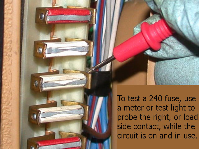
Take a look at the repair photos here, using wire to replace missing foil that was chemically eroded instead of burned -- you'll get the idea of what you need to accomplish. If it looks too difficult, you might have an easier time finding a used cluster to start over with.
http://cleanflametrap.com/speedo7.html
In this forum, if you reply to yourself, only you get the email. Read some other threads, you'll get the hang of the forum and how to post photos.
*Edit: I looked for some youtubes. There are some silly videos out there for sure - a lot of time-wasters. People trying to use "conductive paint" to fix broken foils! Anyhow, this guy is doing it right, and not too tedious: https://www.youtube.com/watch?v=cTnVg6Pmf-U
--
Art Benstein near Baltimore
A man will pay $20 for a $10 item he needs. A woman will pay $10 for a $20 item that she doesn't need.
|
|
-
|
|
|
OK,
So when you are discussing the "foil" you basically mean one of the silver tracks on the circuit board is "slashed" in two? I understand that the board can be removed from the casing with the gauges still attached. Then I assume the next step after that is getting to the other side of the circuit board.
My soldering is fine I do realize however I will need to use a lower wattage iron since I am dealing with much more sensitive material here. When using the wire to bridge, will I actually be using a single strip of wire and connecting?
Thanks Alot
|
|
-
|
|
|
A small piece of foil burned in two, just like when a fuse blows. Examine the foil pathways on your cluster circuit board carefully -- you'll find it. Then bridge that open foil with a small wire, like one strand from a larger stranded wire, and attach it to the foil with solder.
If you have no experience with soldering, practice on some other piece of otherwise trash electronics. Many you-tubes on soldering I presume.
--
Art Benstein near Baltimore
"Doc, I can't stop singing 'The Green, Green Grass of Home.'" "That sounds like Tom Jones Syndrome." "Is it common?" Well, "It's Not Unusual."
|
|
|
|
|
