|
|
|
A little background:
I have two dead cylinders - #3 and #4. Ignition to all 4 has been verified, both with a strobe on individual plug wires and by laying the connected plugs on the valve cover and cranking it over. So my first suspicion was the trigger points. I removed the distributor to the bench and ran a continuity check across both contacts while spinning the rotor. I'm getting good make/break at about 180 deg dwell on each contact. I have yet to pull the injectors w/rail and test the spray in cups. If that looks good I'll check the compression next.
Anyway, I connected an analog volt meter to each injector lead and it shows a constant 12vdc from the moment I turn the ignition on. It continues to show voltage while cranking the starter, I tried leaving the ignition switch ON (not cranking the starter) for a good 30 seconds to see if something would "time out", kind of like the thermal time switch, and stop energizing the injector, but it never did. I did NOT try cranking the starter for a long period of time but maybe I should have.
So my question:
I expected to see a pulsing signal to each injector when I cranked the engine over, rather a constant signal. Is there something in the D-jet logic that feeds a constant signal to the injectors for a period of time when starting a cold engine?
|
|
|
|
|
Not to rain on your parade but are you trying to keep the car stock? If not consider megasquirt or similar or back to carbs...Bosch djet was never a very teliable system, and was replaced with better more reliable system in the 80ss.
Unless I wanted a stock show car I would put something reliable in there
I like my volvos reliable, I don't have contact points in my 68 B18 doing the timing was an unnecessary chore and the engine runs much smoother on electronic (starts better too).
|
|
|
|
|
The only reason for the move from D-Jet to K-Jet was price. The only real problem with D-Jet is failure to read the onwers manual. If you jump in a warm car and pump the gas once or twice, you flooded it. Basically, owners too stupid to read the owners manual gave D-Jet a bad name.
--
69 142S Overdrive + 69 164S Manual
|
|
|
|
|
Not to rain on your rain, but I drove a '72 144 and a '73 142 for many years, both with D-jet. Admittedly it is a crude system by today's standard, but we enjoyed many, many miles of reliable driving with it. Basically I have two problems: 1.) I've been away from the system for a while so I'm getting reacquainted (or should I say "re-antiquated"), and 2.) (the biggest problem) The car has sat for about 18 years and the fuel system got badly varnished-up. Things are looking up though :)
--
Current rides: 2005 Volvo S80 2.5T, 2003 Volvo V70 2.4NA, 1973 Volvo 1800ES (fixed the ignition - now back to the brakes again)
|
|
|
|
|
Chris;
Ditto to your remarks...I have to take exception with Patrick's statement also...the D-Jetronic System was the first...and may have been controlled by an analog control circuit (certainly primitive by today's standard), but it was absolutely reliable on thousands of cars, and not only Volvos...and it was head and shoulders better compared to the nightmare alternative vacuum and thermal timer systems controlling a carburetor (resulting in an unreliable explosion-in-a-vacuum-hose-factory under the hood) of the day.
Cheers
|
|
|
|
|
The earths are bolted together on the intake manifold, not the chassis. B30E earths are bolted to the chassis, on the battery box.(Worse!)
Two dead injectors is the earths OR one of the points in the bottom of the dizzy OR one or one of the wires from the points to the control unit OR worst, a dead power transistor in the control unit.
1. Pull the dizzy, remove ignition points and the rotate slowly and feel if the points gap for each of the injection points feels like it has an even amount of dwell time. Pull the top and side out, clean it, dry it, put some ultra sticky grease on the rubbing surfaces, a minimal amount, and reasseble. The injection points are silver, I think, and last forever, but the rubbing blocks can wear out unevenly.
2. Cross your finger and reinstall.
--
69 142S Overdrive + 69 164S Manual
|
|
|
|
|
I don't know whether you have fixed this problem yet. If not, then read on!
Many years ago when I was collecting info and other stuff for my B20E restoration, I stumbled across an internal wiring diagram for the D jet controller. It was created by a guy who was involved in racing vintage Porsche 914s which also had the Djet system. The basic 4 cylinder Djet controller is the same for all the various cars that it went into (see my final big caveat at the end). The controller was 'tuned' to the individual cars by modifying the resistor and capacitor components that resided on a daughter board attached to the main controller. I have attached the diagram for your reference.
On the top right corner of the diagram, you can see the two output transistors that drive the injectors. You can trace back the circuit from the injector driver transistors, through the NOR gate and edge detector circuits to the distributor contacts. The first thing to note is that controller pins 3 and 4 are paired together on one driver transistor and pins 5 and 6 are paired together on the other driver transistor. According to my Volvo green book service manual, pins 3 and 4 go to injectors 1 and 3 and pins 5 and 6 go to injectors 2 and 4. This injector pairing strikes me as a bit odd; but, it is a batch fire system so injector timing / sequencing is not such an issue. The short take away is that you said your problem resided on cylinders #3 and #4. If the problem originated with the controller or the contacts, I would expect the paired failure to be injector 1&3 or injector 2&4, not 3&4.
In the interest of full disclosure, I ditched my Djet for Megasquirt when I rebuilt my car, so my Djet diagnostic skills will be very rusty. That said, I recall a test procedure where you energize the system and then open and close the throttle and you should be able to hear the injectors operating. If this works for all four injectors, then you know that the injector drivers are working and the wiring from the controller to the injectors is OK. If 3 and 4 are not opening, then check the wiring at the injector ends first, then go to the controller and back-probe the connector to make sure that you are getting output pulses. Pins 3, 4, 5, & 6 should normally be at ground potential and briefly go up to around 3 volts when they send an open signal to the injector (the controller switches the injectors through 6 ohm resistors which limit the current and voltage to the injectors). Pins 3&4 should go up together and pins 5&6 should go up together. During this test, the duration of injector pulses will be very short (probably a few thousands of a second). If you are using a less expensive digital meter, the sampling time on the meter may be slow enough that it may not capture the transition. On an analog meter, it may just show up as a brief flicker of the needle. The best way to check this would be with an oscilloscope. Lacking that, you could get a LED with a suitable voltage dropping resistor to connect to the terminals and watch for it to flash.
I have a 142, so I don't know where the controller is located on the 1800. That said, I recognize that getting at the controller to back probe the connector will probably be a pain. In case you are unfamiliar with the reference to back probing, it means that the tests should be carried out with the controller connected to the rest of the system and that you are testing for voltage on the back of the connector pins. On the up-side, my recollection is that Bosch / Volvo numbered each of the wires in the terminator plug which should help with the trouble shooting.
The final big caveat. The D jet wiring diagram was done up for the Porsche 914 with the VW flat four which has a 1 4 3 2 firing order. Everything that I have seen suggested that the controller internals (with the exception of the daughter board) were the same. However, since I haven't asked the Bosch guys directly, this is all second hand info. As such, my comments about which injectors are paired together on the B20E could be BS. It might be possible that Bosch created a separate unit for the flat four dudes with slightly different internal wiring; however, I don't expect so. All the other terminal numbering on the attached schematic lines up with the terminal listing in the Volvo green book.

|
|
|
|
|
In my case it was cylinders #3 and #4 that weren't flowing fuel, so it didn't correlate to a trigger contact or trigger-to-controller wiring issue. It turned out to be clogged injectors which I have since been able to clear out with a home-spun injector cleaning operation at my work bench.
I fab'd some 8-10" lengths of 1/2" clear tubing (4 of them), slipped onto the injectors, capped at the opposite ends, with little thumb screws in the caps, be which I can release pressure and captured fuel. I then pulled out the distributor, removed the cap, turned on the ignition, and spun the distributor rotor with my finger. I got a click-click, click-click - two clicks with each rotation of the rotor at approx 180 deg spacing. With each click, two injector fire and spray fuel into the clear capture tubes. If I keep spinning the rotor long enough the fuel accumulates in the clear tubes and I cam compare flow volumes.
I've got my fingers crossed that I will achieve a nice smooth idle.
--
Current rides: 2005 Volvo S80 2.5T, 2003 Volvo V70 2.4NA, 1973 Volvo 1800ES (fixed the ignition - now back to the brakes again)
|
|
|
|
|
Are you sure your last name isn't McGiver? I love your enginuity. LOL
Please keep posting.
--
Antique Swedish Steel 71 142E color V#102
|
|
|
|
|
The way my head sees how the injectors works.
Yes, you are getting 12 V at the leads. One of your leads is 12 V, the other is a ground that is connected when the computer wants the injector to open, by completing the circuit to the ground. The way the computer fires the injector is that the circuit is complete when the computer grounds the circuit.
I would check the wiring harness at the distributor trigger points, one of them has gotten worn, maybe the connector damaged. The dist. looks good on the bench cuz your harness is damaged?
--
Antique Swedish Steel 71 142E color V#102
|
|
|
|
|
I considered the trigger points harness connection. I don't know if it means anything, but I get about 25 ohms on each side pin with center pin common to both. Good or bad, at least they're equal and probably both are seeing the computer.
|
|
|
|
|
Chris,
Ron sure can put an idea into words. He knows his stuff, this old equipment will not work properly if contacts and connections are bad. Be sure to check out his web page for more insight into electrical stuff.
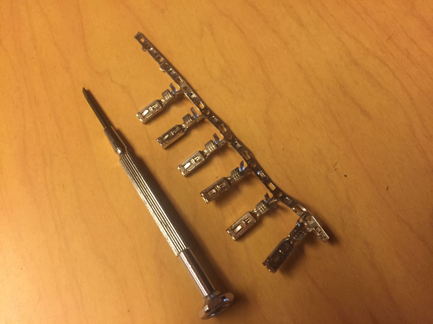
The trigger points on the distributor are one place where two injectors are affected by the same circuit. Your hardware checks out, it is very likely your connection for the trigger points. To repair your wiring you will need to get some female crimp terminals for the corresponding male connector. Get a small jeweler's flat tipped screwdriver that is used to release the individual broken crimp terminal from the trigger point harness plug. Slide the screwdriver into the top surface of the terminal inside the plug, this will hold down the retaining tab on the crimp terminal, then pull out the broken terminal from the plug.
I can not remember where I got my stash of crimp terminals years ago. I pay good money for people like Planetman to find such parts and sell them to me (gives good advice too).
If the terminals in the plug check out OK, I would consider pulling the harness off of the ECU and testing continuity of the trigger point circuit to the ECU.
--
Antique Swedish Steel 71 142E color V#102
|
|
|
|
|
Chris;
I agree with ASS...Injectors get power and Controller completes current path to negative...and since Controller has a resistance in series with transistor which switches this current, Injectors will show 3V across them when transistor pulses ON...remember also: Injectors fire in Pairs...one pair of Injectors not firing suggests an open current path to just those Injectors (wiring/connection problem external to Controller), OR Controller is not firing them in the first place (check Distributor Trigger Contacts and related connections). Clean and check all related connections! Bosch Controllers are highly reliable, so look external to Controller and exhaust all possibilities first before suspecting it!
Link to D-Jet troubleshooting booklet: http://volvo1800pictures.com/document/fuel_injection_fault_tracer/fuel_injection_fault_tracing.pdf
Good Hunting, please let us know what you find!
|
|
|
|
|
"Injectors get power and Controller completes current path to negative."
I understand that. It just seemed odd that when I probed the injector connector with the ignition on, (engine not running) that I saw voltage across the contacts (controller completing path to ground) - trigger points were static at that time. Granted, just seeing that voltage doesn't mean there's enough current to open an injector. I'm suspecting that the controller allows some small trickle to ground even BETWEEN injector impulses. If I put an ohm meter between the ground pin on the injector connector and the chassis, I'm guessing I would see a high level of resistance until I cycle the trigger points, at which time I would see a momentary jump to 0 ohms.
"Injectors fire in Pairs"
That's why I suspected the trigger points when I had TWO dead cylinders.
"check Distributor Trigger Contacts and related connections"
I pulled the distributor to the bench and checked the trigger points function with an ohm meter - all was well for both sets. I also confirmed continuity from the trigger points harness connection to the controller by measuring resistance across left pin and center pin / right pin and center pin. Both circuits showed around 25 ohms.
"Bosch Controllers are highly reliable"
I believe that. This is the third D-jet I've owned over the last 40 years and I was schooled early on that the controller is the LAST piece to suspect.
My whole quandary at this time is why am I seeing a complete path to ground from the injector connector when the trigger points aren't even triggering.
I am going to go back through everything again including cleaning the trigger points and rechecking them for adequate open/close function.
Thanks.
--
Current rides: 2005 Volvo S80 2.5T, 2003 Volvo V70 2.4NA, 1973 Volvo 1800ES (fixed the ignition - now back to the brakes again)
|
|
|
|
|
Chris;
Injectors are not supposed to fire either when Trigger Contacts are static ...but I just looked at Wiring Diag here ( http://www.sw-em.com/1800E%20Wiring%20Diagram.jpg ) again, and both ASS and I had it wrong! (So Sorry!) Controller supplies power to Injectors and one side of all Injectors is tied to Chassis! Please Clean and check this connection for tightness!
I suspect with our incorrect guidance, you might have been interpreting measurements wrong, so please try again!...some notes:
1. Whenever Ignition power is ON, you may only measure Volts (never Ohms)... Ohms can only be measured when component/circuit under test is completely depowered, or an inaccurate/misleading reading will result.
2. Seeing 12V (steadystate), and right across Injector is an immediate indicator of a problem...if that was truly the case (I don't believe it is), Injector would be passing WAAAYYY too much current and burn open!...I suspect something is not as you believe it is, or you are not measuring where you think you are measuring...recheck your method!
3. When Injectors are triggered, they will make an audible click you might be able to hear or pick up with a stethescope, and voltage measured across them at that time should go from 0 to 3V (but since this condition is transient and fast, your meter will probably pick it up, but not indicate it accurately).
Good Hunting! (Sorry again for bad info...it doesn't help with troubleshooting!)
|
|
|
|
|
Ron,
I just looked at the wiring diagram and I see what you're saying about the injector wiring. The way they drew the earth ground symbol in there is kinda weird and easily mistaken. I too was always under the impression that the injectors were wired to provide constant voltage to one pin and that the controller provided the once-per-cycle grounding (of variable duration, influenced by temperature, manifold vacuum, etc, etc.) of the other pin. I believe that on the newer model systems, like our V70 and S80, the controller DOES provide the grounding path.
I'll revisit all my cleaning/testing/head scratching again and figure this thing out!
--
Current rides: 2005 Volvo S80 2.5T, 2003 Volvo V70 2.4NA, 1973 Volvo 1800ES (fixed the ignition - now back to the brakes again)
|
|
|
|
|
