|
|
|
Hi there,
Stephen suggested that I should post my observation/question here.
Background:
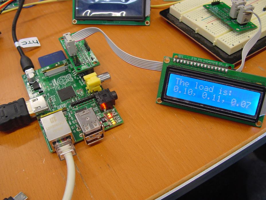
I'm a german based volvo enthusiast, softwaredeveloper and owner of a 1994 945. Some time ago, my instrument cluster developed problems and I tried to fix them myself. Since I was getting tired of monting the unit in the car only to find out it was still broken and the uncertanty it might be something else wrong (broken cabels, faulty speedometer signal etc.)I build my self a testing device (see attached photo). I then started to fix some clusters for frinds and club-members.
Problem:
I recently got the x cluster-instrument where I noticed burned pcb-traces (see attached photo). In most cases I was be able to fix the speedometer by soldering wire where the traces used to be. How ever, in some cases it didn't solve the problem.
I wonder why this happens and I can't figure it out. I would appreciate any help/suggestions.
Best
Gerrit
Burned traces

Simulator

|
|
|
|
|
Dear gerrit1974,
Hope you're well. Solder joint failure occurs because of micro-cracks, usually where solder joins a component to a circuit board. These micro-cracks are far too small to be seen by the unaided eye - develop.
Micro-cracks form as the metal stretches and shrinks. This occurs, because electric current heats the solder ever so slightly. Once the current ceases to flow, the solder cools. Many heating-cooling cycles cause metal fatigue: the metal breaks, often at a joint.
If the flow of current is sufficiently strong - and/or the gap is small enough - electricity can jump the gap (this is how arc welding works). When electricity jumps over a space, it creates an arc, which heats the surrounding areas. Eventually, the heat damages the board to the point, where the gap is so big, that the current cannot jump. At that point, something stops working.
If the micro-crack is found quickly, the break can usually be cured, by heating the solder, until it liquefies (changes from dull gray to shiny silver). As You've found, it is possible - when the solder break is on a circuit board trace (a line of solder) - you can replace the solder with a wire.
Capacitors are another source of failure in these instrument clusters. Capacitors have small amounts of liquid in them. As a result, capacitors can leak or dry-out with time/heat. A leaky/dried-out capacitor causes the device (or part of it) to malfunction or to stop working entirely. The only cure: replace the failed capacitor.
Hope this helps.
Mit freundlichen Grüßen,
Spook
|
|
|
|
|
Hello Spook,
thank you for your reply. I'm familiar with micro-cracks and bad caps. In this case however, something else is going wrong. Btw: PCB-traces are made from copper. In the photo I provided you can see the copper traces. I've checked the fixed traces with a multimeter.
The whole area, where you can see the blank copper was burned. I've still got no clue why and it seems to be a common problem?!
Best
Gerrit
|
|
|
|
|
Dear gerrit1974,
Hope you're well. You're welcome. You're certainly correct that these boards have traces made of copper. On other circuit boards, solder is used, and those are more likely to fail.
I had the same problem as you face, in a speedo in a '93 940. The speedo began to work erratically: the needle would bounce around or, for a few minutes, the needle stayed at "0", before working normally. Finally, the speedo stopped working entirely.
I simply replaced the failed unit with a salvage yard unit. I sent the replacement to an instrument specialist, who checked calibration and re-set the odometer to match that on the failed unit.
Behind the burned area on the failed speedo (that I just examined), there's a capacitor, marked 100 μF, 25V (about 12mm tall x 6 mm diameter). I wonder if that capacitor leaked, and the electrolyte did damage, that caused arcing and eventually, failure. See, for example: http://www.electronicproducts.com/Passive_Components/Capacitors/Failure_modes_in_capacitors.aspx .
Hope this helps.
Yours faithfully,
Spook
|
|
|
|
|
Dear Spook,
there were no signs of leaking, no corrosion, nothing. I did replace the capacitor and I checked it. It still had 75 μF, which is not bad considering the age.
By examinig the burned area, it seems to me, that the trace itself must have heated up the pcb ... but why?
Yours
Gerrit
|
|
|
|
|
Dear gerrit1974,
Hope you're well. As the capacitor is sound, the next likely failure source is a defect in the copper trace's protective coating, likely present from the time of manufacture.
A "pinhole" in the coating - likely not visible without magnification - allowed the copper to oxidize. The oxidation created resistance and so heat, which accelerated the deterioration. Eventually, the heat destroyed what was left of the copper, breaking the circuit, and cooking the protective coating.
Another possibility is that in the copper itself, there was a defect - a micro-crack or some contaminant, that created resistance and turned the trace into a "heating element". Eventually, the protective coating failed, allowing oxidation....
Hope this helps.
Yours faithfully,
Spook
|
|
|
|
|
Hi,
this could definetly explain why it happend, but, since I get more and more PCBs with exactly the same burns ... isn't it unlikely?
Yours
Gerrit
|
|

|
|
Hi Gerrit,
I think I am reading your question correctly: You have just a few traces showing the evidence of heating, and they are always the same traces, in the speedometer circuitry, in every cluster you've examined.
This would not be a fault of PCB manufacturing. It will turn out to be caused by overcurrent in the particular circuits being connected by that flex PC, if the heating is in the middle between components and not focused on one or more of the component leads where solder cracks could indeed be the cause.
What you will need to do is reverse engineer the speedometer itself to determine which components are responsible and why. If I owned 9-series cars I would have by now done this myself as I have for the 240 series which exhibits its own set of electrical faults: http://cleanflametrap.com/#links
I believe if you pursue this and disclose your findings you will do the 7/9 series Volvo owners a great service, as I read about their cluster woes most every week in this forum. After all, this is early 90's technology.
--
Art Benstein near Baltimore
There is no psychiatrist in the world like a puppy licking your face.
-Ben Williams
|
|
|
|
|
Hi Art,
the burns are always like in the picture I provided. Where you can see the blank copper, the mask heated up.
I would love to do the community the favor by reverse engeneering the speedometers-circuits. How ever, I've got no oszilloscope and I'm just a softwaredeveloper with semi-professional electro-engeneering know how.
I've tried to figure out what components are on the board, but, I'm not be able to read the names/numbers of at least 3 of them in this particular area (due overheating and age). I've run out of options and ideas - which is the reason why I'm asking for help in this forum.
Best
Gerrit
|
|
|
|
|
Hi Gerrit,
Looking at your simulator photo I was guessing Raspberry Pi; that you were getting outputs to power up the cluster and send it a tone to mimic the signal from your differential. You're not "just" a developer, and from my point of view, 20-year-old electronics is learned with a small fraction of the brain effort needed to design and code an application.
I think you can do it, and my point of posting here is that you would do it first, as I've seen nothing comparable to your test fixture here or in any other Volvo forums. And I understand you are posting to research this, so you would not have to repeat someone's prior work.
A scope is really helpful to trace through the path from differential to the odometer motor and speed indicator. Some hobbyists I've talked to claim to use a front end and app that makes a smart phone into the storage and display for a useful oscilloscope.
But first I would suggest more searching. Perhaps focusing on the brand of the speedometer, Yazaki? I bet they make stuff for more than just 9-series Volvos, and probably they wind up frustrating owners of other cars with issues like this overcurrent.
I'll keep track of this thread to keep it in view, just in case some one of us is helpful. Wishing you success.
--
Art Benstein near Baltimore
A grenade thrown into a kitchen in France would result in Linoleum Blownapart.
|
|
|
|
|
Hi Art,
no, a raspberry would have to much power to do a task as simple as this. I used an atmel328p. Tweaked the clocks to simulate the signals for the cluster and put it on a selfmade pcb with some additional components.
20Year old electronic is very analog and this is far more complicated than my digital world. Without a proper oscilloscope, a logic analyser and a better understanding of what is going on on the pcb - i will not succeed.
The only thing I could do in this situation is changing the remaining components and test the results. I would have done this, but I don't know the specs of those components with the burned of labels.
... and perhaps more searching
Best
Gerrit
|
|
|
|
|
Hi Gerrit,
I looked at one like yours. There was indeed extensive damage to the traces, but no faulty components, except perhaps the leaky electrolytics.
If you are still looking for circuitry information, I made some notes here:
Notes on 740/940 Speedometer
Thanks to TedV and Spook for providing damaged units to analyze!
--
Art Benstein near Baltimore
Mistakes are the portals of discovery. -James Joyce
|
|
|
|
|
Dear Art Benstein,
Hope you're well. Your analysis and write-up are won-der-ful!!!
Glad to have helped, ever so slightly.
Yours faithfully,
Spook
|
|
|
|
|
Dear Art Benstein,
Hope you're well. If I correctly read gerrit1973's post, he's seen several speedos, which show over-heating and failure in the same area of the printed circuit board, at the back of the speedomenter itself. As I have a 1993 speedo, that failed in the same way, I suggested there might have been a manufacturing flaw, that affected part of the production run.
To what component do you refer, with the words, "by that flex PC"? Do you refer to the flexible, blue circuit card, at the back of the instrument cluster? I ask, because the printed circuit board at the back of the speedometer itself, is not flexible: it is quite solid. It dominant color is the usual medium green.
What would give rise to an "overcurrent"?
Given the way in which Yazaki speedos are built, is it feasible to replace preventively items on the speedo's printed circuit board? I ask, because I've never dismantled a speedometer, so do not know how to access the side of the board, into which components are mounted.
Hope this helps.
Yours faithfully,
Spook
|
|
|
|
|
GM Spook,
Yes, I'm weller than I deserve to be; thanks for asking. Hope you are too.
My apologies for rudely jumping into your thread and, as it seems when I read my own post, challenging your assessment of the situation the OP is presenting. Part of the effectiveness of public forum is the opportunity we get to offer our help to others while exposing ourselves to the criticism which would not obtain in private communication. We hope this should balance out those of us stepping out of our actual experience.
In this case I am stepping out. However, I want to be clear, that the experience I am offering is not with 940 instrument clusters, but with electrical design and printed circuit manufacturing in the 80's and 90's. I'm hoping, since Gerrit has gone to the trouble of building a test fixture for the 9-series Volvo cluster, he will follow through his quest to understand what is overheating the PCB.
It may well be a manufacturing defect Gerrit is pursuing, but the burned substrate and wrinkled copper is not at all likely to be the cause -- just symptom obvious to the casual observer.
It may be a defect in design, or have an external cause, but to get to the root of it, someone will have to understand the circuit -- and so far, reading our 900 forum, I don't see evidence anyone has done that and disclosed it.
I think Gerrit came here hoping someone had already done that work. Looking at the photos in the FAQ, unlike the simplicity of the 240 gauge, there appear to be some application specific chips which may remain "black boxes" to all of us without the design secrets.
Thanks for pointing out the traces in question are on FR-4 and not flexible polyester. I should have looked more closely at Gerrit's photo. As to what might cause too much current to flow in a trace, well, that is the question, isn't it. There's probably a good clue in the fact Gerrit found some speedometers come back to life when the traces are repaired, and others don't.
Those that already have these answers work at Yazaki or VDO, or at one of the many instrument shops. Would be great, but I don't believe they will be sharing in the enthusiast community.
--
Art Benstein near Baltimore
Draw your curves first and then plot your data!
|
|
|
|
|
Dear Art Benstein,
Hope you're well. I defer to your expertise in how printed circuit boards are made.
It seemed (note past tense) strange that only some speedos failed in the specific way described by Gerrit1973. If such failures were common, we'd surely have seen many more posts reporting such failures. It was the infrequency of the failures, that led me to suspect: (a) capacitor failure or (b) a manufacturing defect that affected a discrete number of units.
Gerrit1973's interesting post - involving, as it does, speedos set-up for kilometers - might mean that the fault involves one or more components common to mile-based or kilometer-based speedos. That's why I thought the protective coating put on the circuit board - or the way in which the board was prepared for the coating - might be at the root of these failures.
If Yazaki (or whichever firm, that made the circuit boards) got a batch of coating that was defective, those boards could have been used to make speedos for US-bound cars, or for cars sold in markets wherein the metric system prevails.
You're likely correct that the truth of this matter is known to those, who repair speedometers. If I recall correctly, I sent my speedometer to APT Instruments, in Minneapolis, to be re-set and for a calibration check. It has recored 30K miles since, without any sign of malfunction.
If my hypothesis is correct - there's a manufacturing defect that affected a discrete number of units - then only through very bad luck, should I again experience the same type of speedometer failure. If your hypothesis is correct - that there's a design defect - then all of these units will fail.
Time will tell.
Hope this helps.
Yours faithfully,
Spook
|
|
|
|
|
Dear gerrit1974,
Hope you're well. Not necessarily. Whichever company produced the circuit boards (Yazaki or a contractor) could have received a batch of coating material, that was "off specification", and so had a tendency to pin-hole. There may be other pinholes in the coating, but in places where the pinhole does not do obvious damage.
Alternatively, when the circuit boards were being made, I presume the copper was polished - to remove any surface contaminants - before the protective coating was applied. If the polishing machine was mal-adjusted - or if the post-polishing cleaning of the board was not correctly done - it could have damaged the copper trace or left contaminants on the surface of the copper. Most coatings do not stick well to contaminants. Thus, when the protective coating was applied, the coating did not seal the area over the contaminant. Plainly, the protective coating would not repair any damage to the copper trace.
The bottom line: Yazaki could have made many of these speedometers, with the same defect. That defect may never have been detected. Or, it could have been detected, and the problem cured, but only after many had been shipped.
We may infer, from the fact that these speedos worked for about 20 years, that the defect was not huge.
Hope this helps.
Yours faithfully,
Spook
|
|
|
|
|
Gentlemen,
The Volvo speedometer has proved something of a "lemon", a weak point in what is otherwise arguably one of the sturdiest most reliable automotive pieces ever to grace the road. As these beauties age gracefully, the lack of speedometer function has become quite a concern for obvious reasons, sometimes owners deciding to retire a perfectly good car over the lack of speedometer. The problem of a faulty speedometer can be caused by a bad speedometer itself (usually capacitors) or circuit board malfunction (cracks, etc.).
To this stratified discussion I can add only the following as my area of expertise covers a great many examples of mainly the 7/9 series: early 7 series rarely have a bad speedo, whether made by VDO or Yazaki. The problems come full force starting with the "newer" style dash beginning in 1991. Particularly 1992 models, whether 7 or 9 series, are the worst, they seem to be universally cursed and for the US market usually made by Yazaki. 1993 are somewhat problematic equal to 1994's rate of failure but nowhere as bad as '91-92's. Those by the way are interchangeable, as are 1991 with 1992. 1995 models are less problematic and rarely seem to fail. I cannot speak for models later than 1995 in the 960/S90 line as I don't have enough information but anecdotally one doesn't hear much about problems with these as the early ones from the '90's. Could also be that they are simply newer and as they age they will fail at similar to earlier models rate.
|
|
|
|
|
"As these beauties age gracefully, the lack of speedometer function has become quite a concern for obvious reasons, sometimes owners deciding to retire a perfectly good car over the lack of speedometer. "
That would certainly tug at my heart strings were I already in love with the 9. Still, I am sorry to hear that about anyone's quandary.
In response, I would offer to look into this if Gerrit is OK with it, bringing what experience I have with the simpler 240 instruments into the 90's, if successful. If anyone would like to donate examples to analyze, I can be reached by email: benstein at cleanflametrap dot com. All I can promise in return is communication: when I receive it / first impression / confirmation it is alive or dead, and *if* able to fix it, an offer to return it promptly for postage. This applies to the first few needed to find success and document it for DIY folks, not an offer to do business of any kind.
A lot of good work has already been done; i.e. identifying capacitor leakage and ESR problems, so without any hubris implied, it may be comparatively easy to take the next step, or the private labeled SMT multi-legged critters will require better skills than mine to fathom. Can't hurt to try. Anything made back then has to be easier than the RoHS stuff of today.
--
Art Benstein near Baltimore
People who live on that "New Car Smell" and have their Credit Score memorized better than their own birthday will ALWAYS say you're Crazy. -punk240 Tim
|
|
|
|
|
I do have a couple of faulty speedos laying about I'd gladly contribute along with a C board. I'll contact you to get more info.
|
|
|
|
|
Just to confirm, Thursday, Ted provided me with a pair of 91 speedometers damaged by the capacitor plague. Monday they are repaired and on the way back to him, so I have now firsthand knowledge of what you 7/9 owners are facing, plus a fairly good schematic of the Yazaki.
Using the FAQ document, I can see there's night and day between the 91 and 93 units, so to help Gerrit, I will still need a sample defective 93. Anyone? benstein at cleanflametrap dot com.
--
Art Benstein near Baltimore
The journey of a thousand miles begins with a broken fan belt and leaky tire.
|
|
|
|
|
