Volvo RWD 140-160 Forum

INDEX FOR 10/2025(CURRENT) INDEX FOR 8/2018 140-160 INDEX

[<<]  [>>]


THREADED THREADED EXPANDED FLAT PRINT ALL
MESSAGES IN THIS THREAD


  REPLY TO THIS MESSAGE    PRINT   SAVE 

Crank case ventalation options 140-160 1971


Even with the 'new' cylinder head I am still getting a LOT of smoke out of the tail pipe on heavy deceleration (2500 rpm's or greater). Blow-by?? I'm thinking, from some pictures of other engine bays I've seen, my PCV system may not be routed in the best way.

For a carbureted engine what is the best way to connect or isolate the three locations: 1-metal box low on drivers side of engine. 2- PCV valve on oil fill cap. 3- fitting into carb air filter box.

AND how do I test the oil fill cap to determine if the PCV valve is working?

Thanks,
Wayne


  •   REPLY TO THIS MESSAGE Replies to this message will be emailed.    PRINT   SAVE 

    Crank case ventalation options 140-160 1971

    a LOT of smoke out of the tail pipe on heavy deceleration (2500 rpm's or greater).

    Inlet valve guides and/or seals. When you are decelerating is when the vacuum is highest & that's when the cylinders try to pull oil through the inlet guides.

    PCV: I'd be inclined not to use it. The distribution is not good on you DCD manifold.

    --
    Three 164's, Two 144's, One 142 & a partridge in a pear tree.


  •   REPLY TO THIS MESSAGE    PRINT   SAVE 

    Crank case ventalation options 140-160 1971

    I'm with Dave on the routing.
    Simply blow through the oil cap fitting. There shouldn't be any resistance.

    Are you sure you don't have worn rings causing the blow-by?


  •   REPLY TO THIS MESSAGE    PRINT   SAVE 

    Crank case ventalation options 140-160 1971

    The way it would be set up originally on the '71 -- From the oil separator (box on L/S of motor) a hose goes to a restricted orifice fitting on the intake manifold. Air is supplied to the motor with a hose from the backside of the filter housing to the oil cap. There is no PCV valve on the B20. An earlier model 140 with the B18 would have one. -- Dave


    •   REPLY TO THIS MESSAGE    PRINT   SAVE 

      Crank case ventalation options 140-160 1971

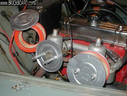
      In some of the pictures I have seen there is a smalll air filter on the oil seperator box and the oil fill cap is routed to the air filter box. Do you know that the reasoning is behind this setup?

      Thanks for the info.

      Wayne


      •   REPLY TO THIS MESSAGE    PRINT   SAVE 

        Crank case ventalation options 140-160 1971

        You may be referring to a late B18.

        At least in the case of my '68 B18...
        1. There is a brass flame trap inserted into the separator canister nipple;
        2. A vertical hose leaves there and goes into a PCV valve;
        3. Leaves the PCV valve and goes into a tee;
        4. One branch of the tee goes to the brake booster;
        5. The other branch of the tee goes to a nipple in the intake manifold which unlike the B20, does not have a restriction;
        6. A second hose goes from the back side of the front air filter to the top of the oil fill cap.

        Basically the routing is opposite on a B18 vs. a B20.


        •   REPLY TO THIS MESSAGE    PRINT   SAVE 

          Crank case ventalation options 140-160 1971

          "Basically the routing is opposite on a B18 vs. a B20." It seems they are very similiar. The B18 is protecting the the crankcase from backfires via the PCV valve. The B20 does the same by the orifice restriction. The B20 provides vacuum to the brake booster via a separate hose going to an unrestricted fitting on the manifold--while, as you say, the B18 has a "T" going to a single open fitting. The oil cap picks up fresh filtered air from the air box on the B20 and accomplishes the same through the front filter of the B18. -- Dave


          •   REPLY TO THIS MESSAGE    PRINT   SAVE 

            Crank case ventalation options 140-160 1971

            Here's what I meant by routing is opposite.

            I'm pretty sure the filtered air on my '72 B20 entered the crankcase at the canister and exited through the oil fill cap and then into the intake through the restricted nipple.
            Vs. the B18 where filtered air entered the oil fill cap.

            Gonna have to go check the green book. An interesting but useless exercise I suppose, but I'm bored.


            •   REPLY TO THIS MESSAGE    PRINT   SAVE 

              Crank case ventalation options 140-160 1971


              "I'm pretty sure the filtered air on my '72 B20 entered the crankcase at the canister and exited through the oil fill cap and then into the intake through the restricted nipple.
              Vs. the B18 where filtered air entered the oil fill cap."
              I took a look in the Green Book I have for the '73 140--probably the same for the '71. I stand corrected--you are absolutely right--air enters through the side canister from the filter housing---exits from the oil cap to the intake manifold. -- Dave


<< < > >>


©Jarrod Stenberg 1997-2022. All material except where indicated.


All participants agree to these terms.

Brickboard.com is not affiliated with nor sponsored by AB Volvo, Volvo Car Corporation, Volvo Cars of North America, Inc. or Ford Motor Company. Brickboard.com is a Volvo owner/enthusiast site, similar to a club, and does not intend to pose as an official Volvo site. The official Volvo site can be found here.