|
|
|
This message was originally posted on the 444-544 forum. But since it pertains to a system sourced from a 240, it is applicable here too - thanks!
I'm back to working on my '65 PV after a couple year pause, now working on the wiring. Since I'm adding a bunch of new electrical items (A/C, OD, radiator fan, cruise) I've decided to modify the system with a new "street rod" fuse block and associated wiring. The fuse block has 8 circuits; 4 switched & 4 unswitched. I was planning on powering the wipers, radio, fuel gauge, and engine warning lights on one of the switched circuits. I'm wondering if this may not be such a good idea, and I would appreciate your input.
The car's original B-18 was replaced with a B-20 sourced from a '75 240, which came with the period-correct Bosch alternator that uses an external voltage regulator. From what I've read about this alternator I believe that the charge warning light circuit may be essential for providing an initial excitation current to get the alternator on-line (I'm really not sure about that). If this is the case, then it may not be such a good idea to have it supplied by a circuit that is shared with other accessories.
Please help me understand the design of this charging system, specifically the function & requirements of the charge indicator light.
Thanks,
Joe in St Louis
|
|
-
|
|
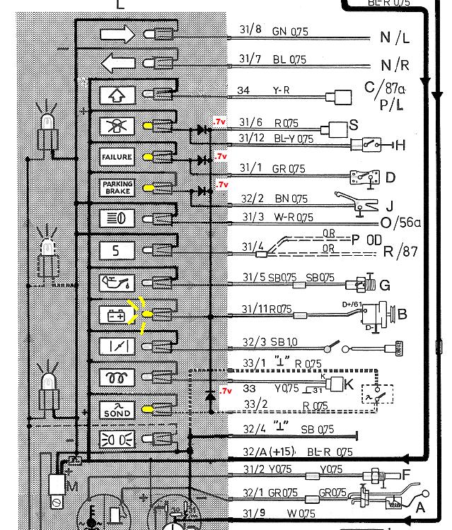
Without knowing the PV's cluster wiring, about all I can do is describe the '75 240 for you, so you can compare the two.
1) The Exciter current to Alternator post 61 (or D+) starts from the Ignition Switch and goes to Fuses 3-4-5 common input side. From Fuse 5 it goes to the Hazard/Signal flasher, and to the instrument cluster as the main +12V supply. This +12 at the cluster is available to several Warning lights, so any that are grounded will light up.
2) The "Charge" warning bulb ground side wire goes to Alternator 61/D+, then thru the brushes & commutator, and finally the Alternator grounding wire. That single bulb current might be enough to pre-exite the alternator, but actually there's more.
3) To provide for complete Bulb-Testing, 3 more bulbs* (not normally grounded at Key On) are diode-connected to the Charge bulb's ground side. So they light up too, and their current adds to the pre-exitation current.
4) Once the alternator puts out voltage, the 61/D+ terminal is no longer a ground, but rises to the Alternator B+ output level. So with +12V on each side, the Charge bulb goes off, as do the other 3, unless/until their normal ground side is made.
* Diode-connected bulbs are:
• Parking Brake
• Brake Failure
• Bulb Failure
--
Bruce Young, '93 940-NA (current), 240s (one V8), 140s, 122s, since '63.
|
|
-
-
|
|
|
sdewolfe,
Your simple drawing answers my question, and reflects the same wiring as depicted in the 140 diagram (green book link). So it would seem reasonable to have fuse protection on the exitation circuit, as it was used on both the 140 & 200 series vehicles.
I am still a bit confused regarding the 68 ohm resister. Is the handbook stating that the alternator would not work correctly without a resister installed in parallel? I don't see a resistor installed in the 140 wiring diagram. Maybe what they are saying is with the resistor installed in parallel the indicator light will illuminate (indicating a no charge condition) if the wire running from it to the voltage regulator opened up, like if it fell off the D+ regulator terminal. Given the same circumstances without the resistor installed, the alternator would not have output and the light would not illuminate unless the loose wire happened to touch a chassis ground.
V/r
Joe in St Louis
|
|
-
|
|
|
sdewolfe,
I took a second look at your simplified wiring diagram and that of the 140, and I believe there in an error in your drawing. You show 3 wires running between the alt & reg; D+, DF, and D- . In addition you show an unmarked case ground on the regulator. The 140 diagram shows both the field (rotor) and stator windings grounding internally to the case of the alternator, and only 2 wires between the reg & the alt; red (D+) from the charge indicator/regulator, and green (DF). The third terminal on the regulator (D-) serves as a ground for the regulator only. Then again, it could be diagrams of two different systems.
Thanks for your time,
Joe in St Louis
|
|
|
|
|