|
|
|
Hello folks,
Finally wired Hella 500 lights... I am trying to wire them to a spare OEM front foglight switch, rather than the Hella switch. Would like to control them without high beams.
I grounded the switch to the driver's side on a bolt next to the hood release.
Grounded the relay to the ground on the driver's side strut tower... green wire powering the switch is taped into radio power. Nothing.
Green wire for power to the switch moved directly to the battery, and grounded the relay, and the lights to the negative terminal, and I had lights for a few seconds, and they were dim.
Walked away for a hour, came back to a dead battery! Any and all help is much appreciated! I really need these lights for driving on back roads at night.
Thanks!
gd
|
|
|
|
|
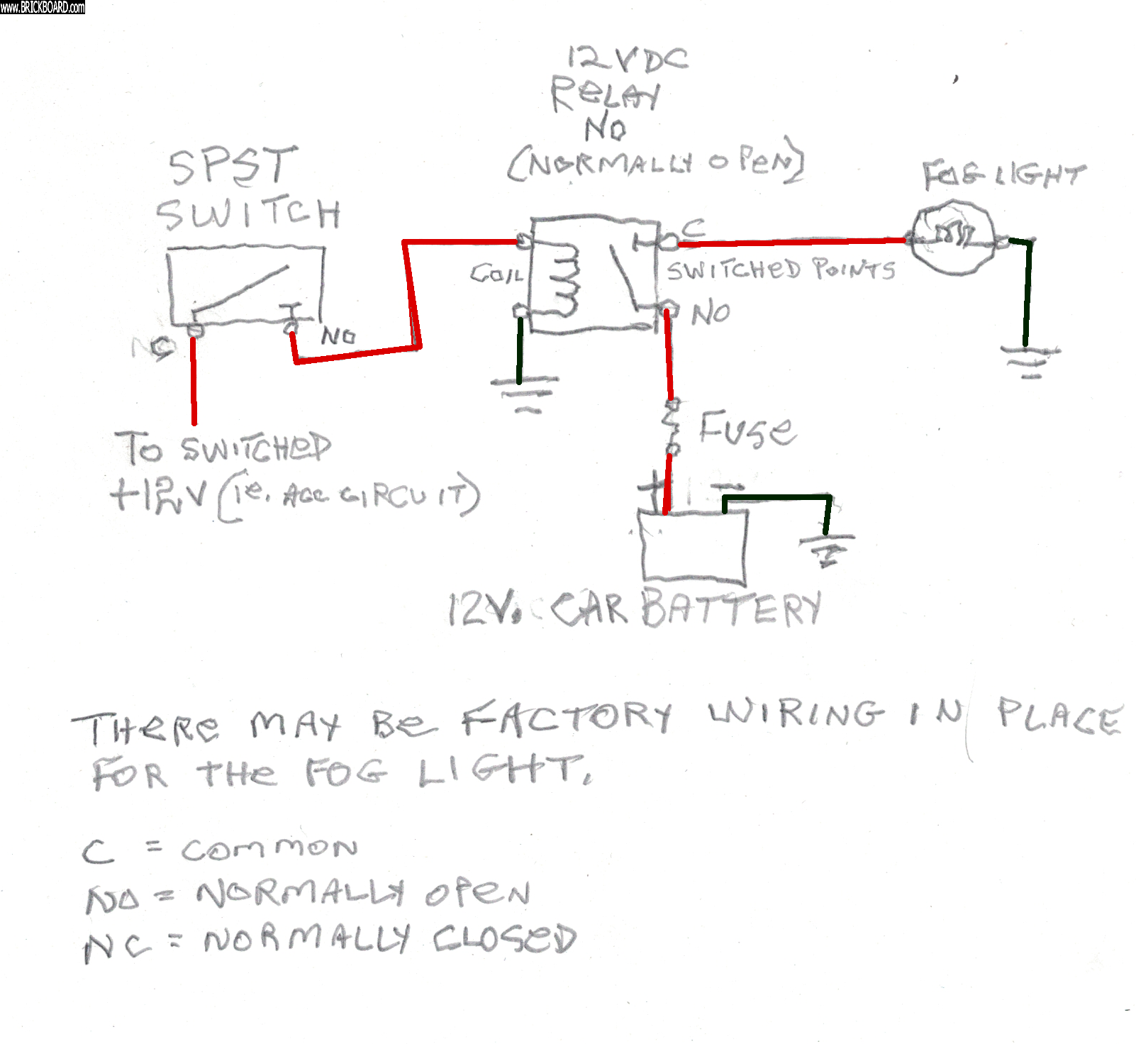
Wire one side of the switch to +12VDC
Wire the other side of the switch to the relay coil
Wire the remaining relay coil to ground
When you flip the switch, the relay points will close.
check the unwired relay points for continuity
switch on = 0.0 Ohms
switch off = infinity -
Wire one side of the relay switched points to +12VDC
This will be a heavy wire maybe #10-12 with an appropriate fuse to the battery,
and put the fuse close to the battery.
Hella will tell you how many amps for the lights, you can use an in-line fuse holder.
The remaining switched points wire from the relay to the lights- (same heavy wire.)
The remaining lights wire to ground. (same heavy wire)
Use the common ground near your battery,
You can find the ground points in the wiring diagram for your car.
Use a factory ground point. Not everything is suitable.
Make sure to secure all wires with tie wraps
Good luck, Bill
|
|
|
|
|
Thanks Bill!
Great points, all. Now to figure out which posts to you on the OE light switch for the lights! I believe it's 3/99…
https://www.carknowledge.info/wp-content/uploads/2017/07/volvo-s70-wiring-diagram-fog-lamp-1-1998.jpg
Cheers,
gd
|
|
|
|
|
Is that a question? Start over and tell me what the problem is.
Don't go at car wiring helter skelter or you can easily set fire to your car.
|
|
|
|
|
Hello Bill,
I've just learned about an accessory connecter potentially being under the dash? This is all new to me. I added an better inline fuse to the harness.
My original idea was to use a factory switch... But at this point I just want to make sure I do this correctly, as to not damage my car, drain the battery- or otherwise over complicate this. I've got a lot of learning,and reading to do
Thanks,
gd
|
|
|
|
|
You can find the 12VDC for the switch to the relay coil part of the circuit
at the radio +12VDC line that's OK.
I made a circuit diagram for you. Tell me if you understand.
Bill
|
|
|
|
|
Hello Bill,
I haven't gotten back to the lights yet today, but I hope to soon. I took a pictures of the relay, and connector.
https://photos.app.goo.gl/LNRVXRBubPNgBbZPA
This is all in the engine bay. I have run the yellow, blue, and greenish blue wires to the switch bank on the drives side.
I attempted to run the wires as per the diagram, no go. I wired in an online fuse, removing the glass fuse that was spent.
Hope to be back at it tonight!
Cheers,
gd
|
|
|
|
|
I urge you to stop trial and error wiring. You're inviting all kinds of trouble.
Thanks for the fuzzy pictures of the bottom of the relay and the connector.
The relay looks like a Volvo pinout.
How about paying attention to the sides of the relay with a magnifying glass?
see if there's a schematic identifying the pins.
Volvo/Hella relays have info on the sides. Look carefully and report.
I found that that the Volvo/Hella relays have a diode accross the coil which means
that you can hook it up backwards.
Where is the info supplied with the Hella kit? What happened to that?
|
|
|
|
|
Hello Bill,
Thanks again for the sound advice!
The plastic fuse holder supplied with the hella kit just made me uncomfortable.
I added the inline fuse with a modern fuse just for safety's sake.
I forgot to add the photo of the remaining
installation instructions that I have...
I bought this kit several years ago with the intention of putting them on my 122, the original instructions have separated from the box.
At the bottom of the photos.
https://photos.app.goo.gl/LNRVXRBubPNgBbZPA
I'll take a better look at the relay. Interesting info on the diode.
Thanks again Bill, really appreciate it!
Cheers,
gd
|
|
|
|
|
Hi Alex,
Your directions are to add extra high beams and very sketchy, they don't include
a fuse which makes it a landmine loose in your car. I'd forget those directions.
Volvo uses a 15A fuse for foglights. This should be tailored to the current requirements of whatever lights you add.
Your relay has numbers on the base that seem to correspond to the Volvo and unversal relay pinouts. Maybe your relay conforms to this pinout?
30 = C Common (switch)
87 = NO Normally open (switch)
85 = Coil
86 = Coil
If there's a diode across the coil then it can be hooked up backwards.
You can use this with the schematic I sent, at your own risk of course.
You can get these relays everywhere for short money and know for sure
what you have.
https://www.superbrightleds.com/cat/off-road-lights/page/1/
Here's the relay you want. It has the diagram and pinout. $2.95
The extra pin is the NC normally closed switch contact, that you wont be using.
https://www.superbrightleds.com/moreinfo/work-light-accessories/12vdc-3040a-5-pin-universal-relay/1667/3844/
They have a pigtail socket for it $1.95 and / or you can connect with spade lugs.
While you're looking around you might decide to install high power LEDs, far better than those antiques that you're struggling with, and the price has dropped way down so that they're affordable.
Bill
|
|
|
|
|
Good morning Bill,
To be clear, these are driving lights, not fog lights. The red wire to the battery has an inline buss fuse, and I've added an inline 25 amp fuse to the greenish blue wire that goes to the switch. If I'm reading the instructions correctly, the greenish blue wire is supposed to be spliced into the high beams. I'd rather not do that.
It was suggested that I splice into the US market "headlight adapters... But I have no idea what those are,and I don't want to do any guessing.
My assumption is that I could tap a switched 12v for the greenish blue wire... Cigarette lighter, radio power.
Driving lights, relay, and switch each to good ground?..
No schematic on the relay. I've added a photo of the front of the relay.
https://photos.app.goo.gl/LNRVXRBubPNgBbZPA
Thanks again for your help and patience.
Cheers,
gd
|
|
|
|
|
Found the original instructions!
https://drive.google.com/file/d/1A76U4O0ADDhGWwbqwmm6RjHJ0ydE9Mkt/view?usp=drivesdk
|
|
|
|
|
Thanks a ton Bill!
I followed you diagram, and double checked my grounds... Then there was light!
I stupidly swapped the volvo foglight switch for the hella,just to see if the the switch worked...it gets power,and lights up... Now no lights!
Checked all the fuses. I haven't a clue. But progress!
Thanks again!
gd
|
|
|
|
|
Hello Bill,
This is wonderful! Thanks for taking the care and efforts to do this. The SPST switch... What is that? The volvo front fog switch? I have a second spare switch if that matters. I think I understand the relay... Mine has power wires (black) going to the lights, a ground wire (blue) a yellow, and greenish wire that go to the switch along with a ground wire (blue for the switch... and the positive (red) wire to the battery.
The switched accessory is any switched power source? I'm guessing that's where my green wire goes.
Thanks again!
gd
|
|
|
|
|
This is wonderful! Thanks for taking the care and efforts to do this. The SPST switch... What is that?
It is a single normally open switch Single Pull Single Throw SPST
It is hooked up as shown in the diagram-
The volvo front fog switch? I have a second spare switch if that matters. I think I understand the relay... Mine has power wires (black) going to the lights, a ground wire (blue) a yellow, and greenish wire that go to the switch along with a ground wire (blue for the switch... and the positive (red) wire to the battery.
This is crazy! The relay needs identification for the coil contacts
and the switching points. Hook it up as shown in the diagram
typically C=common NO= Normally open N= Normally closed
Look carefully at the relay for the pinout.
Relays usually have the pinout on them.
Use the points specified in the diagram.
The switched accessory is any switched power source? I'm guessing that's where my green wire goes.
Yes- 12VDC appears at the radio or acc outlet switched by the ignition switch.
These are fused and safe to use.
More: Volvo fuses fog lights at 15 Amps so that's minimum 14 gauge wire to the lights. more than a single light, hook up in parallel, not series.
The 850 Fog lights work with the low beams only
(High beams are no good in fog)
Leave your phone nr if you're stumped.
Do you have a name? :-)
Bill
|
|
|
|
|
Hello Bill,
I do have a name, Alex... Thanks again for the clarification. The lights came with the relay preassembled. But I see where you're going with the diagram. I'll be up at daybreak give it another shot.
I'm on the east coast... where are you?
Cheers,
Alex
|
|
|
|
|
OK Alex,
You can see my profile at Brickboard...
I'm near Boston.
If there's no markings on the relay, find the Hella info.
Scan it and put it up at Brickboard or maybe it's on-line?
It's a simple circuit, made complicated by a relay with no pinout
printed on it. Then you need to find and share the enclosed directions.
|
|
|
|
|
Profile no longer lists city or state or zip code.
--
Keeping it running is better than buying new
|
|
|
|
|

